|
If you can see this text here you should update to a newer web browser Normal | Highlight & Comment Comments/corrections will appear in yellow like this |
|
CONFIDENTIAL TECHNICAL NOTE NO. F-43
BORESIGHT PATTERNS FOR FIGHTER AIRPLANES
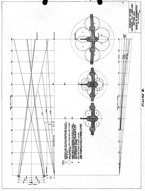
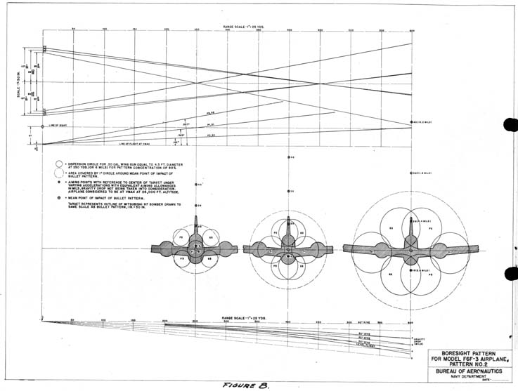
WITH DISCUSSION OF FACTORS AFFECTING AIMING ALLOWANCES. (Figures 14.-9 attached) (Of paramount interest to flying personel;SIC
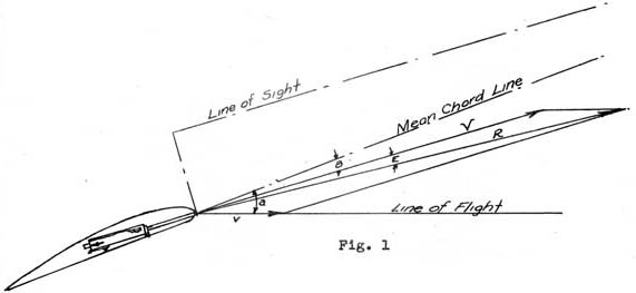
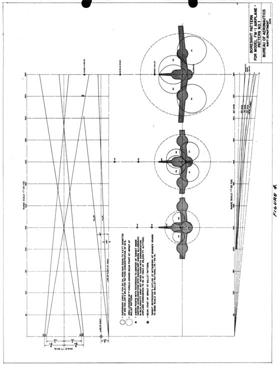
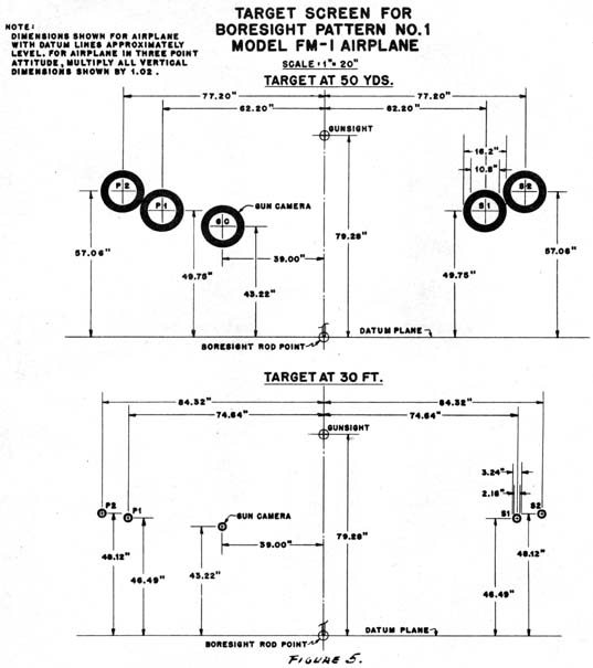
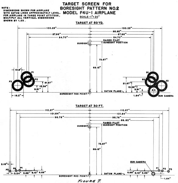
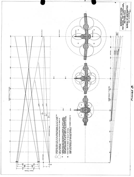
to be read by all pilots 1. Since the advent of multiple-gun installations in fighters, considerable exploration has been carried out to determine what alignment of guns would enable the pilot to make the most efficient use of this increased fire-power. The practice of converging all guns at some one point along the path of flight, commonly referred to as "point bore sighting", although producing heavy concentrations of fire at certain ranges, produces excessive dispersion at other ranges. Furthermore, heavy concentrations of fire at the selected ranges were found to be undesirable in that bullet densities far in excess of the required lethal density were produced, resulting in inefficient employment of the fire-power available. In addition, it was found that limiting the fire coverage to a single plane (i.e. when all guns are aligned parallel to the flight path) penalized the average pilot by requiring refinements in aiming which militated against the pilot's chances of scoring effective hits. 2. The optimum arrangement of guns is that one which will produce the largest circular pattern of a uniform lethal density over the entire effective range. Mechanical limitations preclude the accomplishment of this in our present installations. However, this arrangement which is commonly referred to as "pattern bore sighting", can be approximated by converging each pair of guns at different ranges and elevating each pair of guns by varying amounts. Boresight patterns have been made up on this basis for the Models F6F-3, F4U-1, and FM-1 Airplanes, and, along with appropriate target screen layouts, are shown in Fig. 4 to 9. In arranging the patterns an endeavor was made to obtain patterns with as uniform a density of lethal proportions throughout the effective firing ranges as practicable. A5293 |
|
T.N.No. F-43 CONFIDENTIAL 3. Instructions have been issued to the airplane contractors to deliver fighter airplanes now in production boresighted according to the attached patterns. Modifications will be made to each of the patterns as subsequent experience or considerations indicate the need. It is considered desirable that a uniform boresight alignment be used for each model airplane throughout the service. It is not intended, however, to prohibit deviations from the standard patterns to meet specific tactical requirements. Before departing from the uniform pattern, due consideration should be given to the advantages of standardization which should be weighed against such minor advantages as may appear to exist in variations intended for use during circumstances of infrequent occurrence. 4. Consideration of the factors to be considered in pilot aiming allowance demonstrates the advantages of pattern boresighting over point boresighting. These allowances, taken in the order of their relative importance, are as follows: Allowance due to (a) relative speeds and flight paths of target and attacking airplanes, (b) angle of attack of firing airplanes, and (c) gravity drop of bullet.
-2-
|
|||||||||||
|
T.N.No. F-43 CONFIDENTIAL following vector diagram:
A graphic method of determining the magnitude of this allowance under varying conditions is described in another section of this note.
-3-
|
|
T.N.No. F-43 CONFIDENTIAL
5. On each of the attached boresight patterns is shown plan and elevation views of the extensions of the bore axes of the guns relative to the line of sight and the Vmax flight path. At certain selected ranges the bullet pattern is shown with its mean point of impact at the center of a specified target in order to afford a comparison between the size of the pattern and a known aircraft at various ranges. The attitude of the target aircraft is not to be confused as representing any definite type of approach on the target but is for comparison purposes only. The pattern is also shown in relation to a 1° diameter circle which represents the desirable pattern size of 6 - .50 caliber guns. The test of a pattern, therefore, is the extent to which the 1° circle is filled at all points over the effective ranges. 6. Indicated on the vertical axis of each circle are the aiming allowances, with the corresponding values in mils, which will have to be made in addition to the normal "lead", in order that the mean point of impact of the bullet pattern will fall on the center of the target as shown, if firing is done during maneuvers involving a constant speed (Vmax) and the various "g's" shown. As previously stated, the effect of gravity drop is not considered in determining the allowances shown, nor is any attempt made here to deal with the problem of the magnitude and direction of the "lead" due to the speed and relative path of the target aircraft. Both of these allowances may be at various angles to the vertical axis of the sight, whereas the aiming allowance due to angle of attack will always be applied as elevation along the vertical axis of the sight, since, as can be seen from Figure 1, the bullet trajectory is shifted toward the flight path. 7. A graphic method of determining the proper aiming allowance due to angle of attack under varying conditions is to be found in the Bureau of Ordnance Nomogram shown on Bureau of Ordnance Sketch No. 81081. Used in conjunction with the attitude curves contained in the Erection and Maintenance Manual for each model airplane, it represents a simple and quick method of determing the above allowances. A typical example is given in
-4-
|
|
T.N.No. F-43 CONFIDENTIAL explanation:
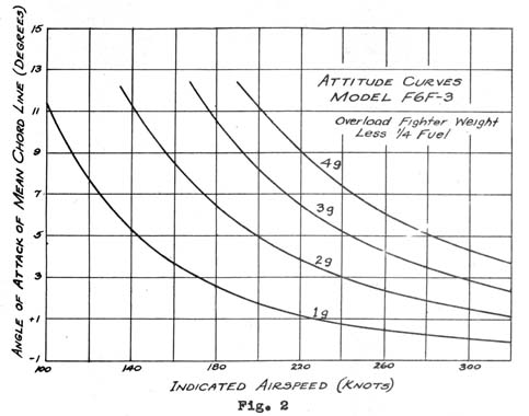
From the attitude curves for the above airplane shown on Figure 2, the angle of attack of the mean chord line under these conditions is 6.5°.
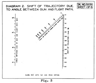
However, in order to use the above mentioned Nomogram, shown in Figure 3 it is necessary to know the angle between the bore axis of the gun and the flight path under these conditions. Therefore, the angle the bore axis of the gun makes with the mean chord line of the airplane (or .47°)* must be subtracted from the angle of attack of the airplane (6*5°), which gives 6.03° as the figure to be used in the Nomogram. * This angle can be determined for any model airplane by sub-tracting from the angle of attack at Vmax the average elevation of the three pairs of guns relative to the Vmax flight path as shown on the appended foresight. -5-
|
|
T.N.No. F-43 CONFIDENTIAL
Using the angle of 6.03° and a true air speed of 329 knots, an aiming correction of 19.5 mils is obtained. However, since all the computations for the Nomogram were made relative to the axis of the gun and are referred to the sight axis, they are correct only when the two axes are parallel. Since this is not the case in our example, the angle at which the axis of the gun is offset to the sight axis (.363° or 6.3 mils) * must be subtracted from the correction obtained from the Nomogram in order to obtain the proper allowance relative to the sight axis, or the true allowance is 19.5 mils less 6.3 mils * 13.2 mils. This, however, is the allowance due to angle of attack only and is applied along the vertical axis of the sight after the normal "lead" due to the target airplane's speed and path has been determined. * Theoretically, each pair of guns should be treated separately due to their differences in elevation. The differences involved are so small, however, that the average elevation relative to the Vmax flight path (or sight line) .363° will serve for all practical purpose -6-
|
|
T.N.No. F-43 CONFIDENTIAL 8. Inasmuch as the delineation of the guns in pattern boresighting determines the overall effectiveness of the pattern, it is important that the guns be aligned as accurately as possible to the targets shown on the boresighting screens. For this purpose, the Bureau of Ordnance Boresight Kit, Mk. 1, should be used. Revised Instructions for the use of this kit will be issued in a forthcoming Bureau of Ordnance O.T.I Bulletin. The diameter of the individual target rings shown on the target screen layouts is such that a narrow ring of light can be seen between the outer edge of the ring and the muzzle opening of the gun, as viewed through the breech adapter of the Kit, when the guns are properly aligned. A cross hair is also included on each target for aligning the gun when the muzzle adapter is used. 9. Nothing in this technical note obviates the necessity for accurate shooting at close ranges to obtain optimum results. There is no substitute for marksmanship. Pilot aiming error increases with range and with approaches requiring high deflection shooting. Pattern boresighting can assist the average pilot in deflection shooting and should increase the effectiveness of the expert pilot at long ranges. However, even with this increased effectiveness, the chance of getting a "kill" with accurate shooting at close ranges is so much greater, pilots cannot afford to discontinue the timetested practice of getting in close where the most effective shooting is possible.  RALPH DAVISON
Rear Admiral, USN Assistant Chief of Bureau
-7-
|
A rotated version of the below image for web viewing is viewable here
|
|
|
A rotated version of the below image for web viewing is viewable here
|
|
|
|
A Rotated version for web viewing is viewable here
|
|