If you can see this text here you should update to a newer web browser
Normal | Highlight & Comment Highlighted Text will be in Yellow.
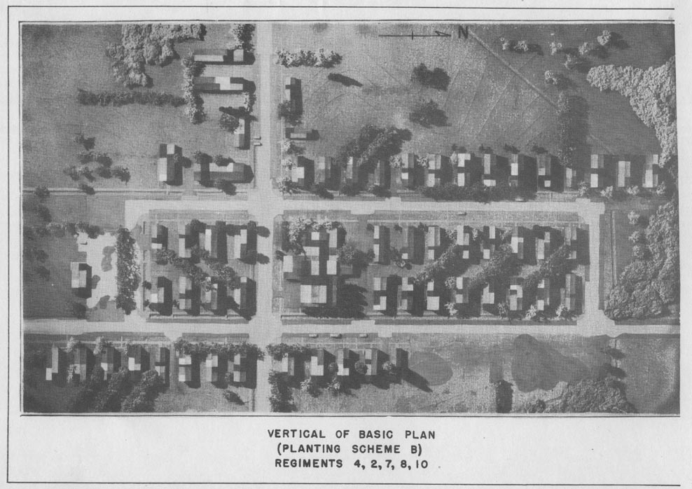
|
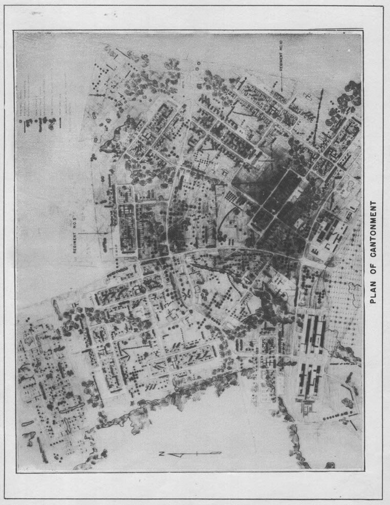
|
|
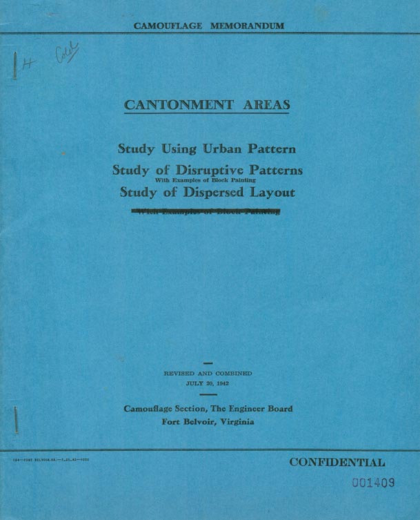
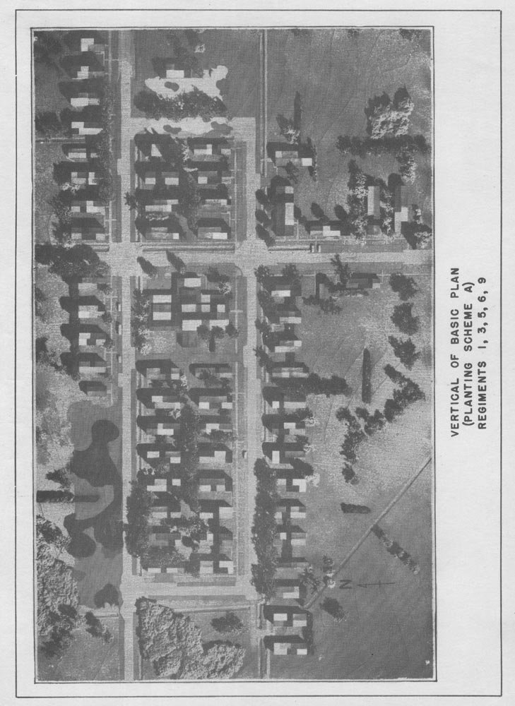
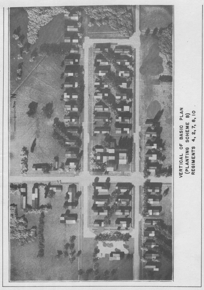
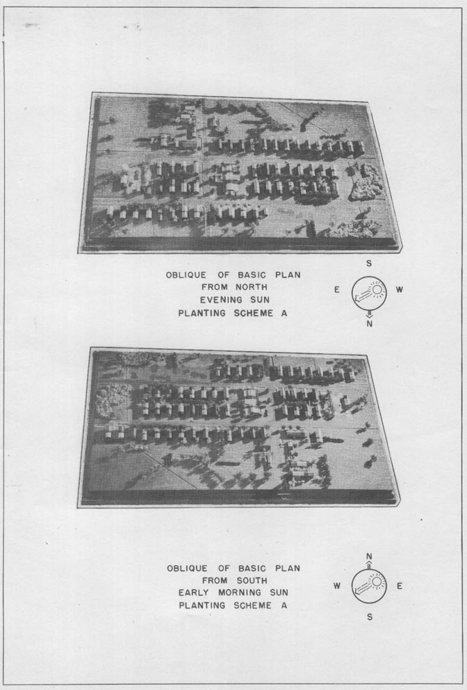
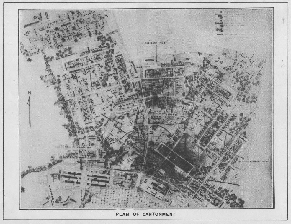
URBAN PATTERN FOR THE CAMOUFLAGE OF A CANTONMENT AREA 1. The following drawing and photographs illustrate the effective use of dispersion and camouflage in the initial layout of an actual cantonment area. 2. The design calls for one basic layout for barracks and facilities to accommodate a regiment. The basic plan varies only in its planting, depending upon its orientation to the sun. 3. Inasmuch as the site selected for this particular cantonment lies on the outskirts of a town, the buildings were arranged in groups to simulate a suburban development. The scale of the buildings has been broken up by paint in geometric patterns. 4. A generous amount of tree planting is used to break up the shadows of the buildings and arrangement and grouping of these trees are in character with suburban developments. 5. The inclusion of trees in the classification yards to simulate an orchard is a promising possibility offered as an alternative to the more expensive cover of nets and will help greatly in concealing an otherwise conspicuous landmark. 6. The plan calls for a minimum of ground paint; consequently the maintenance and cost of camouflage for such a large installation would be relatively small. 7. The designs originated with a private firm under contract with one of the Engineer Department Offices. Specific credit must be omitted for reasons that will be apparent. MARCH 9, 1942 CAMOUFLAGE SECTION FORT BELVOIR, VIRGINIA |
- A rotated version of the below is here
|
|
- A rotated version of the below is here
|
|
- A rotated version of the below is here
|
|
|
|
|
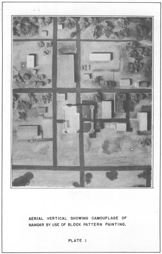
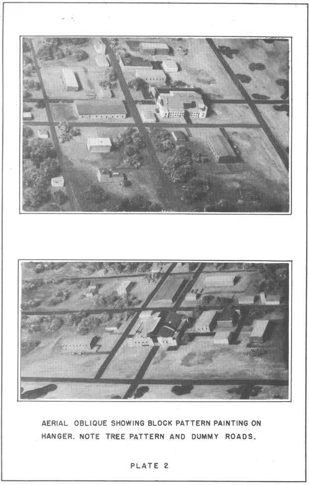
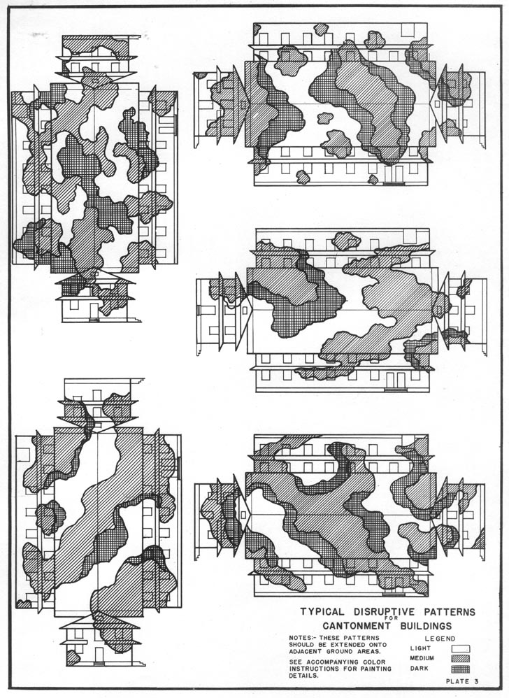
STUDY OF DISRUPTIVE PATTERNS A. Block Pattern Painting 1. The following photographs of a model illustrate the effective use of block pattern painting on a hangar situated in a small shop area. 2. Vertical and oblique views (Plate 1 and 2) show the use of this pattern to divide the apparent outline of the hangar into smaller units, causing it to blend with its natural surroundings. 3. A dummy road has been painted, off-center, across the hangar and the taxiway. Tree pattern painting has been added on the taxiway surface to repeat the existing pattern of trees growing in the shop area. 4. The painted pattern on the hangar has been extended onto adjacent ground areas, in order to distort the definitive pattern of shadow. Cinders or paint may be used to form the necessary pattern on the ground surface. 5. The use of a painted geometric pattern is & logical treatment for protective concealment in this particular area. B. Disruptive Pattern on Barrack Buildings in a Wooded Area 1. Plate 3 illustrates five different studies of a typical disruptive pattern suitable for a wooded area. 2. The pattern in each case is designed to be irregular and large in scale. 3. Pattern is shown extending across the edges and corners of the building in order to obscure the characteristic outline and shape. 4. Definite rules cannot be given for the proper pattern size, because much depends upon the size of the object to be camouflaged, it's surroundings and the type of hostile observation. 5. The accompanying color chart relates to the patterns on Plate 3« Colors indicated were selected for use in the Carribbean area and should be varied to suit local conditions.
|
|
COLOR CHART To accompany Plate 5 Typical Disruptive Patterns, Cantonment Buildings. LIGHT COLORS No. 4 Field Drab No. 1 Light Green MEDIUM COLOR No. 2 Dark Green No. 7 Loam NOTES These colors (excepting black) have been designed for reflection of the infra-red rays, and will retain this property when blended with white or with each other. However, this property will be lost if different pigments are used. The pigmentations given above are approximate and their proportions will vary with different paint vehicles and pigment sources. The pigments used in the preparation of these colors are all of domestic origin and are commercially available. The mixtures given are for the general guidance of the agencies procuring, producing, and applying the paints. Revised (12-12-4l) according to Corps of Engineers, U. S. Army, Tentative Specification No. T-1213.
|
|
|
|
|
CANTONMENT AREAS STUDY OF DISPERSED LAYOUT
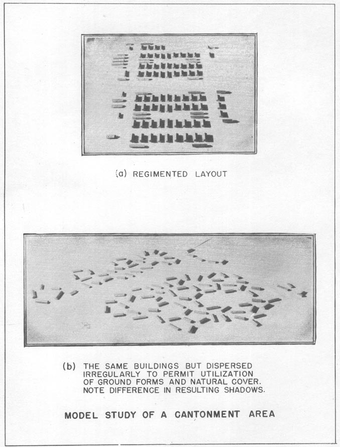
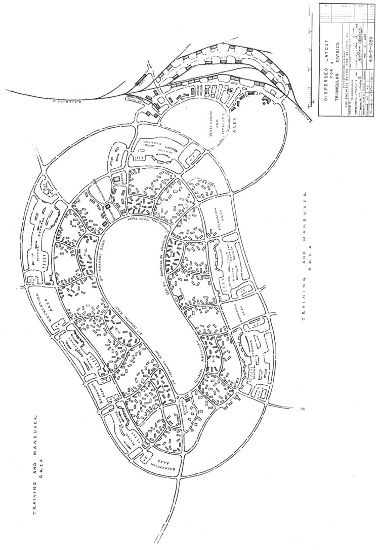
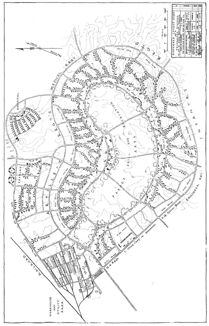
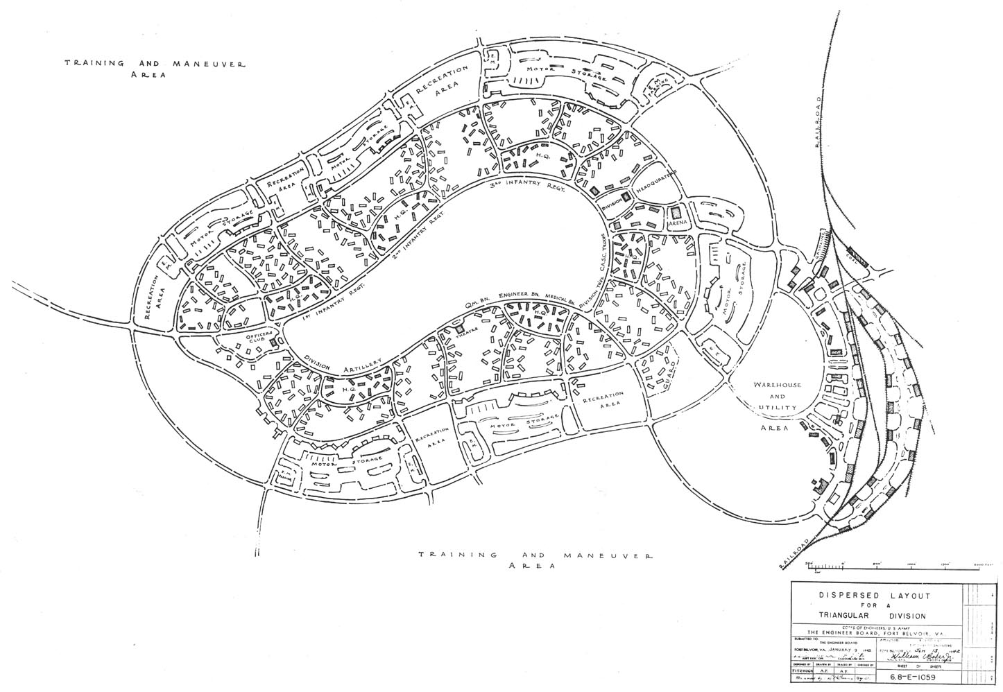
1. The following drawings are suggestions for dispersion within large contonment areas. Visibility and concentration of buildings has been reduced by rotating the buildings and arranging them to fit the contours of the ground, while organizational grouping has been retained. 2. The area of the dispersed layout is approximately fifteen percent greater than the standard rectangular layout. In,, the case of the cantonment at Camp Forrest, a careful estimate indicated thet the cost of roads and utilities would be increased about eighteen percent. 3. Since the cost of building remains unchanged, the net increase in the total cost of the project, excluding compensating economies, would be about four percent. The compensating economies are the elimination of drastic grading by the following of contours, the preservation of surface growing soils, the conserving of trees with their high military concealment values from the oblique, and the reduction in visibility by dispersion over e greater area. 4. The accompanying model study of a cantonment area demonstrates-the high visibility of repeating shadows in a rectilinear arrangement, compared to the varied shadows formed by varied orientation of the buildings.
|
|
- A larger, rotated version of the below is here
|
- A larger, rotated version of the below is here
|
SOURCE:
National Archives & Records Administration, Seattle Branch
Record Group 181, Puget Sound Naval Shipyard Captain of the Yard Passive Defense Files
Transcribed by RESEARCHER @ LARGE. Formatting & Comments Copyright R@L.
Passive Defense Home |
Miscellaneous Home |
Researcher@Large Home