If you can see this text here you should update to a newer web browser

Normal | Highlight & Comment Highlighted Text will be in Yellow, but there are none yet


RESTRICTED   ORDNANCE PAMPHLET NO. 806
(First Revision)


MACHINE GUNS


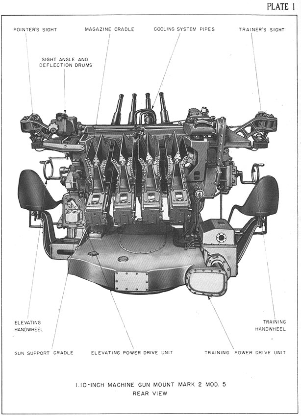
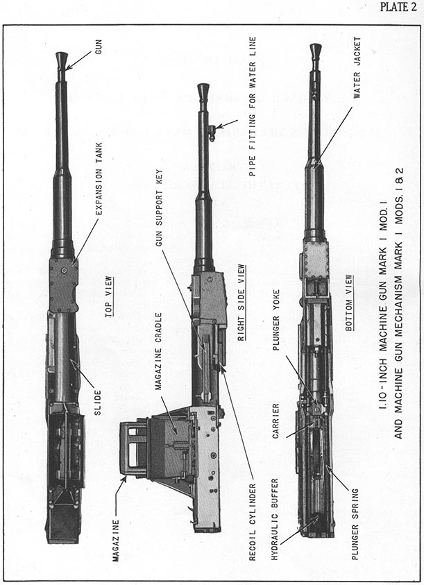
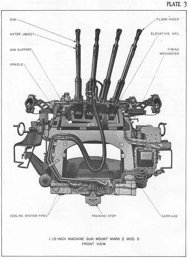
1.10-INCH MACHINE GUN, MARK 1, MOD. 1

AND

1.10-INCH MACHINE GUN MECHANISM MARK 1, MODS. 1 & 2


DESCRIPTION


4 JULY 1944


This Publication is RESTRICTED and will be handled in accordance with Article 76, United States Navy Regulations, 1920


NAVY DEPARTMENT
BUREAU OF ORDNANCE
WASHINGTON, D. C.


4 July 1944

RESTRICTED

ORDNANCE PAMPHLET NO. 806 (First Revision)

1.10-INCH MACHINE GUN MARK 1 MOD. 1 AND
1.10-INCH MACHINE GUN MECHANISM MARK 1 MODS. 1 AND 2

     1.  Ordnance Pamphlet No. 806 (First Revision), issued for guidance of the Naval Service, describes, illustrates, and provides operating and maintenance instructions for the gun and the machine gun mechanism of all 1.10-inch gun assemblies in service.

     2.  The operating precautions, trouble analysis routines, and servicing instructions compiled in Ordnance Pamphlet No. 806 (First Revision) are specific directions as to the proper use and care of the 1.10-inch machine guns. The instructions supplement the general regulations of the Ordnance Manual. For purposes of uniform practice in Service use of this weapon they are to be used by all schools, training centers and gun mount personnel.

     3.  Ordnance Pamphlet No. 806 (First Revision) supersedes the original edition dated August 1941, all copies of which are to be destroyed. The revised text includes references to the following Ordnance publications:

O.P. 598-1.10-inch Quadruple Machine Gun Mount Mark 1 and Mark 1 Mods.
O.P. 717-1.10-inch Range Table.
O.P. 772-1.10-inch Quadruple Machine Gun Mounts Mark 2 and Mark 2 Mods.

     4.  Ordnance Pamphlet No. 806 (First Revision) is a RESTRICTEDpublication. It is to be handled in accordance with provisions of Article 76, U. S. Navy Regulations, 1920.


G. F. HUSSEY, JR.
Rear Admiral, U. S. Navy,
Chief of the Bureau of Ordnance


TABLE OF CONTENTS


CHAPTER I
  Page
FUNCTIONAL DESCRIPTION
  Gun . . . . . . . . . . . . . .   1
  Mechanism . . . . . . . . . . .   1
  Slide . . . . . . . . . . . . .   1
  Breech housing. . . . . . . . .   1
  Recoil and breech operating
    mechanism . . . . . . . . . .
  3
  Magazine cradle . . . . . . . .   3
  Firing mechanism. . . . . . . .   3
  Firing mechanism gear . . . . .   3
 
CHAPTER II
1.10-INCH MACHINE GUN, MARK I MOD. 1
  Gun barrel   5
  Gun yoke   5
  Table of general data of gun and
    ammunition.
  5
 
CHAPTER III
1.10-INCH MACHINE GUN MECHANISMS
   MARK 1 MOD. 1 AND MARK I MOD. 2
  Gun mechanism units   7
  Assembled units   7
 
CHAPTER IV
SLIDE
  Slide detail   9
  Cooling chamber   9
  Recoil cylinder   9
  Rear plate   9
  Carrier buffer   9
 
CHAPTER V
BREECH HOUSING
  Housing detail   11
  Cocking cam   11
 
CHAPTER VI
BREECH MECHANISM
  Carrier   13
  Safety lug   13
Pivot pin   13
  Cam lug   13
  Breechblock assembly   13
  Breechblock   13
  Locking wedges   13
  Extractor   16
  Cartridge case support   16
 
CHAPTER VII
  Page
FIRING MECHANISM
  Firing pin   19
  Sear lever   19
  Cocking lever   19
  Sear   19
  Firing plunger   19
  Firing cam plate   19
    Firing cut-out cam and rod   19
    Table of cam equivalents   20
    Fire   20
    Stop fire   20
    Firing cut-out   20
  Recocking mechanism   21
 
CHAPTER VIII
AMMUNITION FEEDING MECHANISM
  Magazine cut-out mechanism   23
  Carrier stop   23
  Carrier stop sear   23
  Feed sear and feed scar lever   23
  Safety lever or anti-double loader   23
  Feed plate unit   24
  Cartridge guide plate   24
  Cartridge stop plungers   24
 
CHAPTER IX
MAGAZINE CRADLE MECHANISM
  Cradle supporting brackets   25
  Magazine cradle   25
  Ammunition release cam   25
  Locking pawl and locking trips   25
  Magazine lifters   25
  Cradle latch   27
  Magazine   27
 
CHAPTER X
RECOIL SYSTEM AND BREECH OPERATION
  Recoil spring   31
  Gun yoke   31
  Piston rod assembly   31
  Recoil cylinder assembly   32
  Carrier plunger assembly   33
  Expansion tank   34
CHAPTER XI
COOLING SYSTEM
  Cooling liquid   35
  Water jacket   35


VI TABLE OF CONTENTS

CHAPTER XII
Page
MACHINE GUN OPERATION
  Preparation for firing   37
  Feeding   37
  Ramming, firing, and ejecting   38
    Ramming   38
    Breech locking   38
    Firing   38
    Breech unlocking   38
    Cartridge case extracting and ejecting   38
  Cocking   39
  Safety features   39
  Recoil and counterrecoil   39
    Recoil action   39
    Counterrecoil action   40
  Carrier reciprocating action   40
 
CHAPTER XIII
INDICATOR DIAGRAM
  Analysis of indicator diagram   41
 
CHAPTER XIV
ASSEMBLY AND DISASSEMBLY
  Disassembly   45
    Removing guns from mount   45
    Slide   45
    Breech mechanism   46
  Assembly   46
    Slide   46
    Carrier buffer   47
    Recoil spring   47
 
ASSEMBLY AND DISASSEMBLY-Continued.
  Assembly-Continued Page
    Cartridge guide plate   47
    Magazine cradle   47
    Breech mechanism   48
    Firing mechanism   48
    Ripple firing   48
    Cooling system   49
 
CHAPTER XV
SERVICING INSTRUCTIONS AND OPERATING
    TROUBLE ANALYSIS
  Servicing instructions   51
    To replace water jacket packing   51
    To replace recoil cylinder packing   51
    To replace carrier plunger packing   51
  Servicing before and after firing   52
    To bore sight   52
    Care of gun bore   52
    To fill recoil cylinder   52
    To vent recoil cylinder   52
    To drain recoil cylinder   52
    To fill carrier hydraulic buffer   52
    Flushing of cooling system   52
    Lubrication   52
    Routine immediately before firing   52
    Operating trouble analysis   53
    Routine after cease firing   53
 
CHAPTER XVI
TOOLS AND ACCESSORIES
  Description and use   55


ILLUSTRATIONS
Plate Page
Gun mount, rear view Faces page 1
Gun and mechanism, top, side and bottom views 2
Gun mount, front view 4
Breech housing 12
Carrier and breechblock assembly-right and left side views 14
Carrier and breechblock assembly-top and left side views 15
Locking wedge action 17
Firing mechanism-schematic 18
Magazine cut-out mechanism-schematic 22
Magazine cradle 10  26
Magazine, magazine cradle and brackets-assembled 11  28
Magazine cradle mechanism-schematic 12  29
Magazine 13  30
Piston buffing action 14  32
Ramming sequence 15  38
Indicator diagram of automatic firing action 16  42
Tools and accessories 55-59
Section of gun loaded and ready to fire 17  Appended
Relation of parts during recoil and counterrecoil 18  Appended
General arrangement-sections 19  Appended
General arrangement-sectional isometric 20  Appended
General arrangement 21  Appended
Lubrication chart 22  Appended


MACHINE GUNS


THE 1.10-INCH MACHINE GUN, MARK 1, MOD. 1


AND


MACHINE GUN MECHANISMS, MARK 1, MODS. 1 AND 2


CHAPTER I

FUNCTIONAL DESCRIPTION

GUN

  1. The 1.10-inch machine gun, Mark 1 Mod. 1, is a 75 caliber, single tube, alloy steel forging or centrifugal casting (see pl. 2). These guns are quadruple mounted on a horizontal axis in the 1.10-inch machine gun mount, Marks 1 and 2 and modifications. (See pls. 1 and 3). (For description of mount see O.P. 598 for Mark 1 and Mods, and O.P. 772 for Mark 2 and Mods.)

  2. The guns have a muzzle velocity of 2,700 feet per second, a horizontal range of 7,300 yards, and a ceiling of 16,000 feet. Each gun fires a 0.917 pound, detonating-fuzed tracer projectile at an average rate of 150 rounds per minute. The gun and housing recoil together about 3.25 inches.

Mechanism

  3. The machine gun mechanisms, Mark 1, Mods. 1 and 2, are full automatic, hydraulically (recoil) operated, liquid-cooled mechanisms. The design permits side by side multiple mounting, with independent ammunition supply and case ejection. It differs from other automatic machine gun actions in that it combines the following features:

  (1) A quick and smooth functioning breech mechanism, free from the vibrations that would be induced by parts moving vertical to the bore axis.
  (2) Continuous application of force throughout the full strokes of extraction and ramming.
  (3) An arrangement that automatically stops the ramming action when the ammunition supply is exhausted,

and resumes ramming and automatic firing when the supply is replenished.
  (4) Hand recocking without opening the breech.
  (5) Arrangements for stopping the mechanism action with the breech either open or closed and for resuming automatic operation from either position.
  (6) A safety device to prevent ramming if extraction is not completed.
  (7) A visible indication showing whether the gun breech is open or closed.
  (8) Cartridge feed and case ejection without the conventional arrangement of moving pawls and fingers.
  (9) An ammunition supply in conveniently handled units arranged to provide uninterrupted feed permitting continuous fire. This ammunition supply and case ejection permit the mounting of several guns side by side.

Slide

  4. The slide is a bronze casting with a cylindrical forward section and a box shaped rear section. It provides gun slide and recoil piston borings, an integral expansion tank, and supports for gun mechanism and ammunition cradle. (See pl. 2 and pl. 19 appended.)

Breech Housing

  5. The breech housing is a nickel steel forging, cylindrical at the front end with two channel-

1


FUNCTIONAL DESCRIPTION 3

shaped side walls extending to the rear and bridged across on top at the rear. (See pl. 4.) These elements form a longitudinal slot extending from the cylindrical body to the rear end of the housing. In this slot the breechblock and carrier parts reciprocate.

Recoil and Breech Operating Mechanism

  6. The recoil and breech operating system is a spring and hydraulic mechanism which controls the movement of the reciprocating parts. It develops, stores, and releases the energy of that movement for the operation of the breech mechanism. The breech mechanism moves in a long rearward stroke under a continuously applied hydraulic force and forward under spring action. Magazine Cradle

  7. The magazine cradle assembly automatically feeds a continuous ammunition supply into the cartridge guide plate. It consists of two supporting brackets bolted to the top of the slide, supporting the magazine cradle, two replaceable magazines, and controlling latches. (See pl. 2.)

Firing Mechanism

  8. The firing mechanism is of the percussion firing type mechanically operated. It is cocked automatically during the ejection stroke, but may be recocked by hand. The firing mechanism gear of the mount is used to control the firing of one or more of the guns. Each gun is equipped to be fired independent of the firing gear on the mount. Provision is made for single shot firing.

Firing Mechanism Gear

  9. The firing mechanism gear on the mount is a system of bell cranks and linkages connecting a lever on the left side of the mount with the four gun firing mechanisms. It is spring loaded to return the lever to the unfired position when it is released. The firing cut-out mechanism lever is located on the upper right surface of the gun cradle for safety use. For a description of this mechanism see O.P. 772.


CHAPTER II

1.10-INCH MACHINE GUN, MARK 1 MOD. 1

GUN BARREL

  1. The gun barrel is a single tube, alloy steel forging or centrifugal- casting, bored, rifled and chambered for 1.10-inch fixed ammunition (see pl. 21 appended).

  2. The gun bore is 82 inches from breech face to the muzzle. The chamber is 8.74 inches long from the breech to the band slope, and contains 10.5 cubic inches. For 73.06 inches the diameter of the bore is 1.10 inch, having 12 rifle grooves of uniform width and uniform right hand twist of one turn in 30 calibers.

  3. The external surface is machined for mounting the breech housing, gun yoke, flash hider, and recoil spring compressor nut and to form a forward cylinder for gun slide in recoil. In addition two shallow recesses are milled in the breech face for the extractor and safety lever of the breech mechanism. (See pl. 20 appended.)

  4. For 8 inches the breech end of the gun barrel fits into a bore in the front end of the breech housing. A securing gland screws into the breech housing at the front end of this bore and fits against a shoulder around the gun barrel. The securing gland is locked in place with a screw dowel pin. The breech face of the gun barrel is drilled and reamed to take a 0.5-inch diameter dowel pin. This pin registers with a similar hole in the housing on the right-hand side. This arrangement rigidly locks the barrel and housing together. (See pl. 21.)

  5. The muzzle end of the gun barrel is threaded for 0.60 inch with a 0.09-inch undercut (or threaded for 0.75 inch without an undercut) to receive the flash hider. This is a conical steel tube extending 6 inches forward from the muzzle of the gun to a final outside diameter of 3.075 inches. An annealed copper gasket forms a flame seal between the muzzle face and the flash hider which is locked in place by a 0.25-inch setscrew.

Gun Yoke

  6. The gun yoke fits around the gun barrel against a shoulder 28.8 inches forward of the breech. Just in front of the yoke the barrel is threaded to receive a securing nut. A key locks the yoke in

position and prevents turning of the gun barrel within the yoke.

  7. In front of this securing nut the barrel passes through a bearing in the front end of the slide. The rear part of the recoil spring sleeve fits into an annular recess around the front of this bearing. This sleeve is long, thin walled, and flanged on its rear end. The rear of the recoil spring fits around this sleeve and presses against the flange. (See pl. 21.)

  8. The gun barrel is encircled by the recoil spring from the point where it passes through the slide bearing to 11 inches from the muzzle where the barrel is threaded to receive the recoil spring compressor nut. Between the gun yoke securing nut and the recoil spring compressor nut the barrel is a cylinder 2.4 inches in diameter and forms the forward barrel slide surface.

  9. From the spring compressor nut threads to the muzzle the barrel is 1.85 inches in diameter.

  10. The interior and exterior of the gun barrel is chromium plated, except for the chamber which is left unplated.


SOURCE:
National Archives & Records Administration, Seattle Branch
Record Group 181, Puget Sound Naval Shipyard Captain of the Yard Passive Defense Files

Transcribed by RESEARCHER @ LARGE. Formatting & Comments Copyright R@L.

XXX Home | Section Home | Researcher@Large Home