If you can see this text here you should update to a newer web browser

Normal | Highlight & Comment Highlighted Text will be in Yellow, but there are none yet


From: Commander in Chief, United States Fleet
 
To: Commander in Chief, United States Pacific Fleet
Commander, Seventh Fleet
Commander, U.S. Amphibious Forces, Pacific
Commander, Amphibious Training Command, Pacific
 
Subject: Rocket Launcher, CIT Type 49 - Description of.
 
Reference: (a)   Cominch Conf. memo. to VCNO FF1/S79-4 Serial 02823 dated 16 August 1944.
(b) OSRD Abriged Catalog Entry - CIT Launcher Type 49
 
Enclosure: (A) Copy of Reference (b)

     1.     In connection with Reference (a), Enclosure (A) is forwarded herewith.

     2.     Complete description of rocket ammunition and launchers will be provided.


  W. S. DeLANY
Assistant Chief of Staff


Copy No.     CIT   
IEC 14

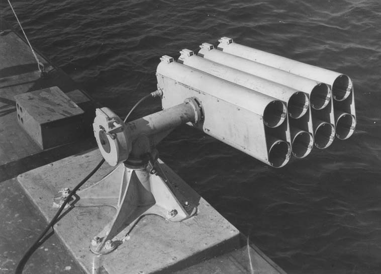
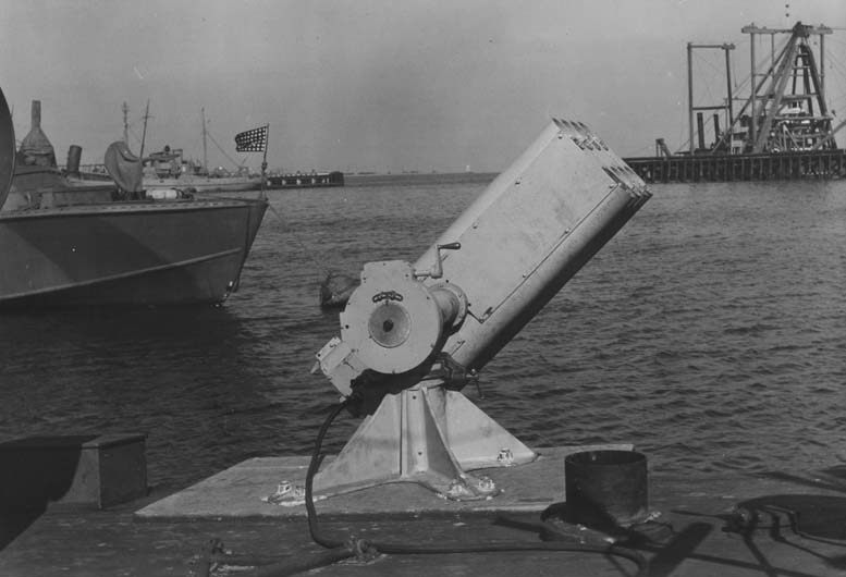
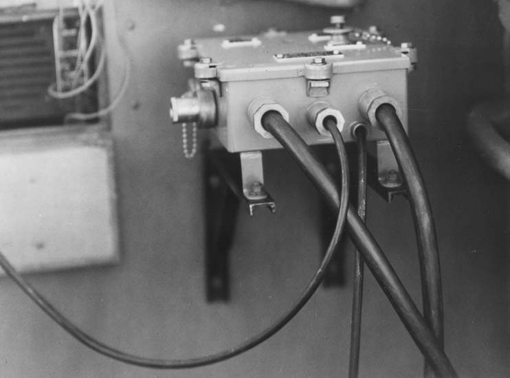
Abridged Catalog Entry

CIT LAUNCHER TYPE 49

LAUNCHER: CIT Type 49
 
ROCKETS:

High Velocity (1530 ft/sec) ll,000 yd max range.

5.0" SSR Model 26, GP with nose fuse, to be used for high angle fire in long range barrage.

5.0" SSR Model 30, SAP, with base fuss, to be used in flat trajectory angle fire at short range when a semi armor—piercing shell is required. This round, with appropriate heads, could also be used for special effects at high altitudes.

Medium Velocity (750 ft/sec) 5000 yd max range.

5.0" SSR Model 27, NP, with nose fuse, to be used at high-angles for medium range barrage.

5.0" SSR Model 28, GP, with nose fuse, to be used at high-angle for medium range barrage. This round, with appropriate heads, could also be used for special effects at moderate altitudes.

 
DESCRIPTION:

Eight 48-in. launcher barrels each with three internal stainless steel guide rails spaced l20° apart around the axis of the barrel. A latch on the breech of each barrel holds the rocket securely in place, releasing the round when it is fired. If the loaded launcher is stowed in the inboard position, these latches may be locked by passing a long rod through a hole in each of the latches in the upper row and a second similar rod through the holes in the latches of the lower row. This prevents any possible shifting of the rounds in the barrels. These locking rods are removed from the latches just before the launchers are swung to the outboard position in preparation for an attack. The barrels are arranged in two rows of four each, one row being above and the other below the horizontal supporting shaft.

The adjustment of the QE of the launcher barrels is obtained by the use of a self—locking worm gear drive which rotates this shaft. The worm gear and support bearing assembly are enclosed in a housing mounted on top of a vertical shaft whose lower end fits into a large cast aluminum pedestal. This pedestal forms the base of the entire launcher assembly


CONFIDENTIAL           -2-


and is bolted to the deck. The vertical shaft rotates on bearings in the pedestal and is arranged so that it may be locked in two positions, inboard for loading and for stowage and outboard for firing. It is held in these positions by two locking pins, one of which moves into place automatically by spring action when the launcher is swung into place. The second pin is then inserted manually by screwing it in. When the rails are locked in the outboard position they are parallel to the center line of the boat. They are therefore trained by the helmsman who points the boat directly at the target. Both the helmsman and the firing officer will use aircraft type reflector sights.

 
WEIGHT: Loaded 1136 lb, unloaded 400 lb.
 
USE: To be used on PT boats for attacking Jap barges and similar targets at close range (approximately 300 to 1000 yd) with flat-trajectory fire. Can also be used at high angle of fire for long-range barrage directed at bivouac areas, shore installation, and barge concentrations.
 
MOUNT:

Two launchers will be mounted on the PT boat, one starboard, one port. They will be mounted either near the bow just forward of the charthouse, or else nearly amidships in the position now occupied by the forward torpedo racks, depending on which location proves the more suitable.

 
QUADRANT
ELEVATION:
Capable of all quadrant angles, since the worm gear drive permits the launcher to be swung through 360° about the horizontal axis. Adjustment is made by using the crank projecting from the gear housing. One revolution of this crank changes the QE by 50 mils. The QE is indicated on a dial. Minor changes in QE may be made, after the crank adjustment has been set, by increasing or decreasing the speed of the boat slightly, thereby causing the bow to raise or drop.
 
FIRING
CONTROL BOX:
The Mk l3 Firing Panel is used. This has a 16-position manually-operated switch, a firing push button, and a combination power switch and removable safety plug. The 24—volt ship's storage battery provides the firing current. The pair of launchers may be connected for firing 16 single rounds in sequence or they may be put in a parallel circuit which would enable the firing officer to fire the rounds in pairs, one round being fired from each launcher.
 
FIRING RATE: The rounds may be fired as rapidly as the firing officer can press the firing button and selector switch, approximately two per second singly or four per second in pairs. The time needed to load the launcher will vary with the condition of the sea. Under favorable conditions the minimum time needed would probably be about 90 sec.


CONFIDENTIAL           -3-

 
TACTICS:
(TENTATIVE)

Present tactics appear to favor approaching the target area at a reduced speed of 5 knots with the launcher QE preset to correspond with the desired attack speed and range. This slow speed is employed to eliminate the formation of a wake that could be readily observed by enemy aircraft, especially in regions where the water is phosphorescent. Once the target is located and the firing is about to commence, the need of concealment is not so important and the attack is pressed forward at a speed of about l5 knots in order to get better steering control for training the boat and its launchers at the target. The planing angle of the boat varies appreciably with changes in its speed, increasing nearly 5° between 5 and 30 knots. Consequently, it is expected that the launcher QE would be preset for a range of about 500 yd at a 15 knot speed.

After the initial ranging shots are fired, minor corrections of the QE can be made more rapidly by changing the boat speed, and hence the planing angle, than by using the elevating gear, adjustment.

In case a large change in QE is necessary, a crew member must make the adjustment at the launcher by operating the elevating crank. Not more than 30 sec should be required for this operation.

The most difficult part of the attack is to keep the boat aimed at the target, since the roll and pitch, combined with the relatively poor rudder control at low speeds, make it hard to hold the boat on the precise course necessary to keep the target lined up in the reflecting sights of the helmsman and firing officer.


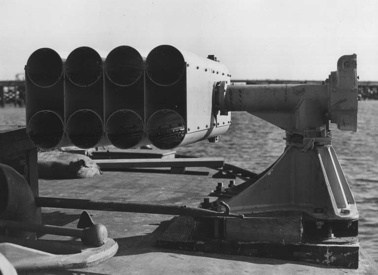
Fig. 1. Launcher stowed inboard in starboard bow location, looking forward.


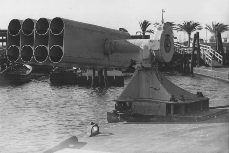
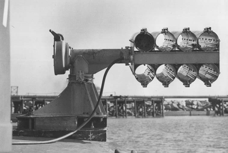
Fig. 2. Launcher outboard in firing position (QE 5°) in starboard bow location. Looking aft.


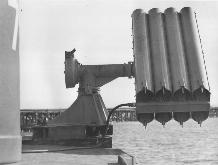
Fig. 3. Same as Fig. 2, looking forward


Fig 4. Same as Fig 2, except QE 45°


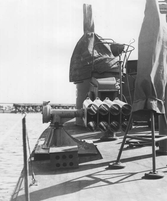
Fig. 5. Launcher stowed inboard in port amidship location, looking forward.


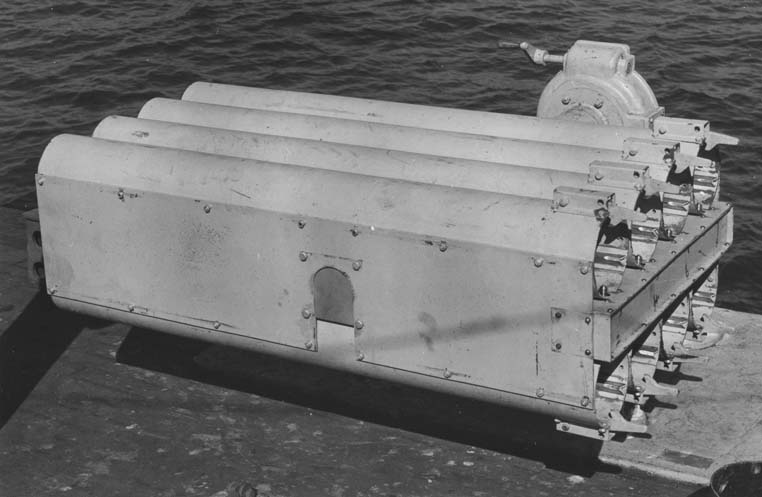
Fig. 6. Launcher stored inboard, showing firing contacts and retaining pawls


Fig. 7. Launcher outboard in firing position (QE 5°) in port amidships location.


Fig. 8. QE 45°


Fig. 9.


SOURCE:
National Archives & Records Administration, College Park
Record Group 313, CINCPAC Confidential Files 1943-45

Transcribed by RESEARCHER @ LARGE. Formatting & Comments Copyright R@L.

Ordnance Home | Researcher@Large Home