If you can see this text here you should update to a newer web browser

Normal | Highlight & Comment Highlighted Text will be in Yellow.

RESTRICTED


Ship: VIBURNUM (AN 57)
Cause of Damage: 1 Mine
Date: November 1944
Class: AN 38
Standard Displacement: 1275 tons
Length Overall: 194' 6"
Beam:  37' 0"
Draft Before Damage:  11' 6" forward; 13' 6" aft
Launched: 26 April 1944


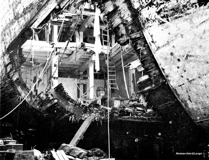
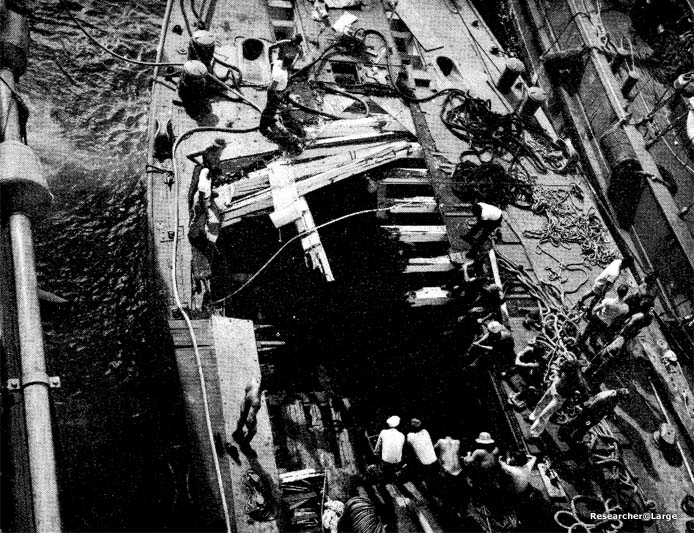
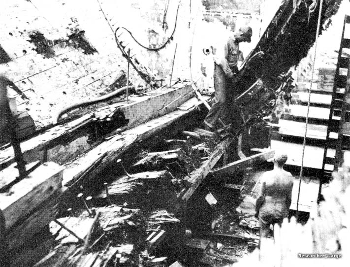
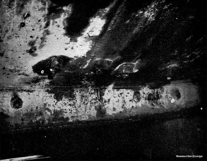
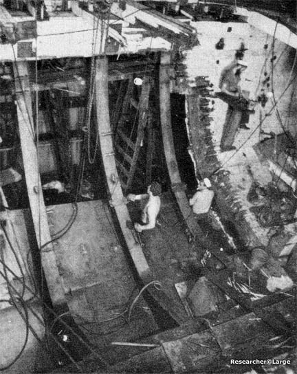
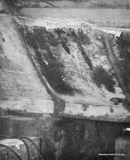
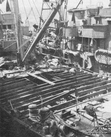
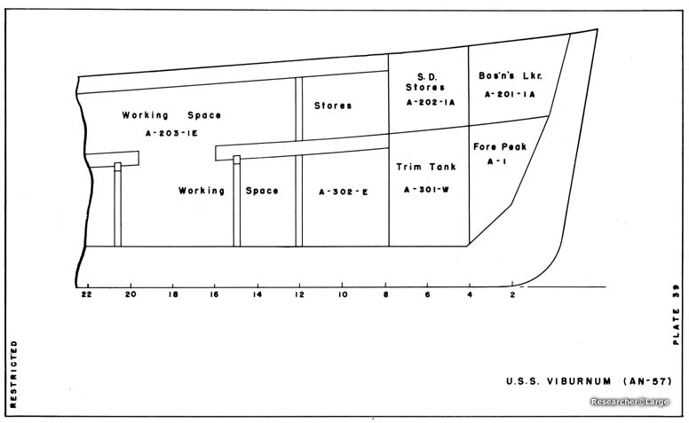
1.     VIBURNUM, a wooden hull ship, struck a contact mine at frame 12 starboard. The explosion tore a hole in the shell between frames 6 and 17 starboard and from the keel to the second deck side longitudinal (Photo 82), tore a hole in the second deck and in the port side of the main deck (Photo 83). The keelson (Photo 84) and planking about 3 feet to port were shattered between frames 7 and 18. The bolts pulled loose in connections between the shell and all bulkheads forward of frame 30. All spaces forward of bulkhead 30 flooded to the waterline as the ship took on a draft of 21 feet forward; 10 feet aft.

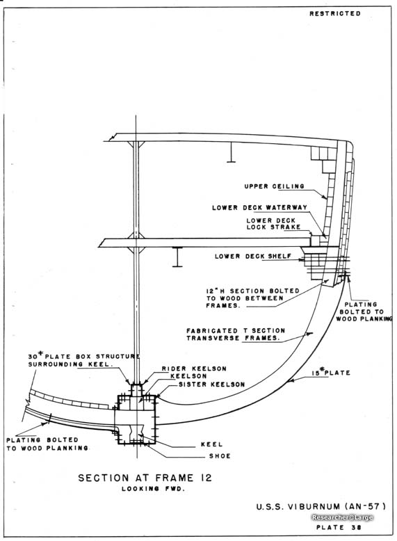
2.     The crew undertook salvage measures that succeeded in reducing the drafts to 17' 6" forward and 12' aft. In order to accomplish this, the horns were cut off and moved to the fantail, the anchor chains were moved aft, debris was removed from the damaged spaces forward, and A-1W and the space between bulkheads 27 and 30 were made tight so that the spaces could be pumped dry. This made it possible to drydock VIBURNUM in ARDL 32 (Plate 38).

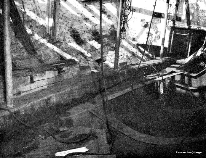
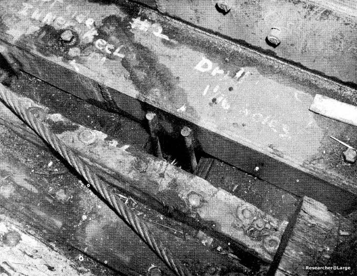
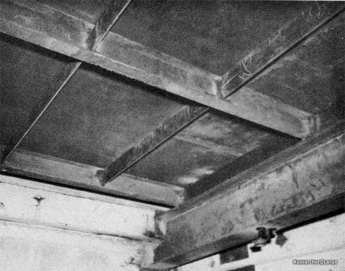
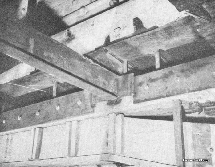
3.     After VIBURNUM was drydocked, debris and damaged planking was cleared away and repairs were undertaken. Since neither materials nor trained personnel required to effect wood repairs were available, it was necessary to use steel. The keel was encased in 3/4" steel plate, which was bolted to it and extended well beyond the ends of the damage in order to provide structural continuity. The box structure surrounded the keel completely on the starboard side (Photo 85), but terminated on top of the port bilge ceiling (Photo 86). Bolts through the shell plating were used in conjunction with bolts through the wood structure to attach the steel box (Photo 87).

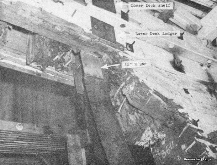
4.     Transverse framing in the damaged area was replaced by fabricated steel T sections (Plate 39). The lower end of these frames were welded to the box girder encasing the keel structure. Their upper ends were welded to 12" H sections that were inserted and bolted through the lower


RESTRICTED - 89 -


RESTRICTED


deck shelf and lodger between frame spaces (Photos 88 and 89). Shell plating was welded to the steel keel box girder and to the frames. It was welded to the bow sheathing at the forward end. Other boundaries overlapped and were bolted to undamaged wood structure. A canvas gasket impregnated with red lead was used to make connections between wood and steel hull structures watertight.(Photo 90).

5.     The damaged portion of the lower deck was replaced by a steel deck. Deep I beams were used to replace the longitudinal 9" x 9" timber girders and served as intermediate supports for transverse channel sections which terminated in specially designed structure that landed on the lower deck shelf and was bolted to the lower deck lockstrake (Photos 91 and 92), The replacement of the main deck was similar to that,of the lower deck, with deep longitudinal I girders replacing the 9" x 9" longitudinal timbers. Transverse channels were landed on the main deck shelf and were given intermediate support by the longitudinals (Photo 93). Pipe stanchions were installed between the hold, lower and main decks to provide additional support.

6.     Although these repairs were intended to enable VIBURNUM to proceed to a mainland yard, they proved so successful that the vessel continued to serve in the forward area for the duration of the war.


- 90 -
RESTRICTED


Photo 82: VIBURNUM (AN 57)
Looking aft at hole in starboard shell plating.
 
Photo 83: VIBURNUM (AN 57)
Hole in main deck, port side.
 
Photo 84: VIBURNUM (AN 57)
Damage to rider keelson and sister keelson.
 
Photo 85: VIBURNUM (AN 57)
Steel box structure replacing keel structure and welded connection of steel transverse frames.
 
Photo 86: VIBURNUM (AN 57)
Termination of steel box structure at port bilge ceiling and bolted connections of box structure.
 
Photo 87: VIBURNUM (AN 57)
Bolted connections of steel box structure.
 
Photo 88: VIBURNUM (AN 57)
Fabricated T section transverse frames.
 
Photo 89: VIBURNUM (AN 57)
Connection between transverse frames and wooden hull structure.
 
Photo 90: VIBURNUM (AN 57)
Connection of steel shell plating to bow sheathing, box keel girder, and wood structure.
 
Photo 91: VIBURNUM (AN 57)
Attachment of longitudinal girder to transverse lower deck beam end bulkhead B.
 
Photo 92: VIBURNUM (AN 57)
Landing of transverse lower deck beams on lower deck shelf and connection to lower deck lockstrake.
 
Photo 93: VIBURNUM (AN 57)
Structural support for main deck.
 
Plate 38: VIBURNUM (AN 57)
Section at Frame 12, looking Fwd.
 
Plate 39: VIBURNUM (AN 57)


SOURCE:
National Archives & Records Administration, Seattle Branch
Record Group 181, Entry 59A-271 "13th Naval District Bremerton, Washington" General Correspondance 1947-1958
"Structural Repairs in Forward Areas During World War II" -BuShips Booklet dated December 1949.

Transcribed by RESEARCHER @ LARGE. Formatting & Comments Copyright R@L.

Repairs in Forward Areas Home | Ships Home | Researcher@Large Home