
If you can see this text here you should update to a newer web browser
Normal | Highlight & Comment Highlighted Text will be in Yellow.
|
|
|
U.S.S. NEVADA Torpedo and Bomb Damage December 7, 1941 Pearl Harbor
|
|||||||||||||||||||||||||||||||||||||||||||||||||||||||||||||||||||||||||||||||||||||||||||||||||||||||||||||||||||||||||||||||
There are 51 photographs and 12 plates appended to this report. The reader with limited time for study of the full report will find a comprehensive summary in Sections I, II and VIII, together with Plates I and II and Photos 1 to 6, which have been arranged for a quick review of the case.
|
||||||||||||||||||||||||||||||||||||||||||||||||||||||||||||||||||||
|
FOREWORD 1. U.S.S. NEVADA was struck by one torpedo and five bombs on December 7, 1941. There were two severe fires on board. The ship got underway and was beached. Nearly all compartments below the main deck flooded. Two months elapsed before she was floated and docked. She arrived at the Navy Yard, Puget Sound, three months later for final repairs and modernization. This report deals with the damage in detail, and with the salvage and temporary repairs in general, during this five-month period. 2. There are naturally numerous conflicts of evidence and some points must remain obscure. A representative of the Bureau of Ships visited the ship on arrival at the Navy Yard, Puget Sound, interviewed many of the personnel and carefully inspected the ship. This report is based upon the results of this investigation and the referenced correspondence. The plans are based on those submitted by the Navy Yard, Pearl Harbor, with reference (d). 3. Plates I and II and the first six photographs have been prepared to facilitate a preliminary survey of the principal events, together with the following narrative. NARRATIVE (Plates I and II; Photos 1 to 6) 4. U.S.S. NEVADA was moored starboard side to the interrupted quay F-8 at Pearl Harbor on the morning of December 7, 1941. The depth of water here is about 40 feet. The weather was clear, with scattered clouds. 5. The Japanese air raid commenced with dive-bombing of the Air Station on Ford Island just before 0800, and a torpedo plane attack on the battleships followed immediately. NEVADA was struck by a torpedo on the port side between the two forward turrets at about frame 41, approximately 14 feet above the keel. This occurred at about 0810. The innermost torpedo bulkhead was opened at seams and butts and compartments below the first platform deck between frames 30 and 43 (on the port side only) began to flood. The ship gradually listed four or five degrees to port. Counterflooding reduced the list to nearly zero. 6. Orders were issued for the battleships to sortie. NEVADA had already started warming up, and got underway at about 0840. The torpedo plane attack had lasted only ten to fifteen minutes. Dive and high-level bombing continued, however, and was in progress as NEVADA backed away from her berth and swung out to clear ARIZONA at berth F-7. The subsequent movements are shown on Plate I, and a diagram of the torpedo and bomb hits is given on Plate II. ARIZONA'S forward magazines blew up and VESTAL got clear before NEVADA left. 7. The ship had nearly reached the channel entrance and was about opposite CALIFORNIA at berth F-3 when signals were received not to leave the harbor. The engines were stopped and - 3 - |
|
preparations made to anchor. This was at approximately 0900. PENNSYLVANIA, from her position in No. 1 drydock; reports that a flight of about fifteen bombers approached from the southeast at an altitude of 10000 to 12000 feet. Roughly two-thirds of the flight apparently observed NEVADA and swerved off to attack her, while the remainder continued on to attack the ships in the dock.* The group which attacked NEVADA apparently did so with no preconceived plan, for the bombs came from various angles and at various degrees of steepness, many from dives, as shown by Plate II. 8. Five bombs struck the ship almost simultaneously. No one can give the sequence of these hits. Certainly all landed within two or three minutes. The Chief Engineer, returning to the ship by boat, saw a close cluster of three bombs falling toward NEVADA, followed by three smaller objects (which may have been parts of the release gear) about 100 feet behind the bombs. Two struck the forecastle over the wardroom country near frame 15, one of which went out through the side at the second deck level and caused near-miss damage to the starboard side, while the other penetrated to the gasoline tank and exploded within the ship between the tank and the shell on the port side. Another struck near the port waterway forward of No. 1 turret at frame 25, penetrated to and ricocheted from the second deck and blew large openings in the main and upper decks. A fourth struck the port director platform in the foremast and exploded at the base of the stack on the upper deck. The other bomb exploded on the superstructure deck directly over the crew's galley. For convenience in future reference, the hits are numbered from 1 to 5 in the above order, it being understood that the actual sequence is unknown. 9. Fires broke out immediately. Men standing by to anchor on the forecastle were blown overboard and the anchor gear was wrecked. It was imperative to get clear of the channel, as other ships were leaving the harbor. The ship was therefore beached near the floating drydock which contained the destroyer SHAW. 10. Pressure on the firemain was not enough to fight the fires, especially the intense one in the foremast structure, and two tugs were summoned to assist in firefighting. The wind was from the east, and the stern of NEVADA tended to swing out across the channel in the way of departing ships. Shortly after 0900, the magazines of SHAW exploded** and showered the decks of NEVADA with debris. These various circumstances resulted in a decision to move to the other side of the channel. 11. A tug pushed the stern farther around and the bow floated off. It appears that the tugs moved the ship most of the way across the channel, and that the engines were used only at the last, when they were backed until the stern was hard aground. This was at about 1030, or an hour and a half after the bomb hits. Flooding was progressing aft, though at this time the third deck was dry abaft No. 2 barbette (frame 48) and the central crew space between frames 30 and 48 on the third deck apparently had only a little oil in it. 12. The after magazines had been flooded while the ship was passing ARIZONA. This was done by mistake; there was no need to flood these magazines. Flooding of the forward magazines was commenced at 0920, while the ship was aground near - - - - - - - - - - - - - - - - - - - - - - - - - - - - - - - - - - - - - - - - - -
4 |
||||||
|
18. Gasoline was forced up from the tank ruptured by bomb No. 2. It is believed that vapor collected forward of bulkhead 8-1/2 on the main deck. The fire already raging in the officers' country must have caused the vapor explosion which occurred on Sunday afternoon, and which resulted in more structural damage on the main and upper decks. There may have been intermittent minor vapor explosions. It was late Monday afternoon before this fire was extinguished. It was extremely stubborn, re-igniting when apparently out. The two forward bomb holes and a long split in the upper deck were stuffed with mattresses, and the fire was finally brought under control by smothering with steam supplied from the tugs. 19. Salvage work was undertaken at once. The three bomb holes in the hull (exit hole and near-miss hole caused by bomb No. 1, and the hole near the forefoot caused by bomb No. 2) were covered with external wooden patches. A large patch was made for the torpedo hole, but it did not fit properly and was removed before the ship was docked. 20. The decks were gradually unwatered by gasoline-driven salvage pumps. Stores, provisions, auxiliary machinery, motors and ammunition were removed as the various compartments were pumped out. Toxic gases were unfortunately encountered which killed two men. All surfaces were covered with fuel oil, and the task of cleaning the ship was a formidable one. 21. NEVADA again became waterborne on February 12, 1942 and was docked on the 18th. Photos 1 to 6 illustrate her history up until then. Temporary repairs were made to the hull and the machinery was put into limited operating condition. She steamed to the mainland at twelve knots, arriving at the Navy Yard, Puget Sound, on May 1, 1942. 22. A discussion of the types of bombs and of the torpedo used is given in paragraphs 130 to 133. The conclusions are that bombs 1, 2, 3, and 4 were of the 250-kilogram general-purpose type, carrying 133 pounds of explosive; that bomb No. 5 was a light fragmentation bomb weighing about 60 Kg. and using an impact firing pin; and that the torpedo charge was under 500 pounds and possibly as low as 337 pounds(The "Type 91 mod 2" torpedoes used during the attack on Pearl Harbor featured an explosive charge or 452 lbs., or 205 kg). 23. The damage which the enemy inflicted on this ship was comparatively superficial. The main machinery was not affected and most of the armament could continue in action. The ship sank because of deficiencies in watertight integrity, by virtue of the lack of watertight bulkheads on the second deck and failures of boundaries and fittings elsewhere which should have been watertight but were not. These converted a fairly simple repair job into a salvage and overhaul problem. STRUCTURAL DAMAGE A. Structural Damage Caused by Torpedoes (Plates III and IV, Photos 7 to 10) 24. The torpedo evidently exploded on impact at frame 41 on the port side, about 14 feet above the keel, which placed it between the first and second platform decks. There was a dull explosion accompanied by a noticeable but not a serious shock. No derangements of machinery or other equipment were observed. - 6 - |
|
25. The protective structure in this vicinity is shown on Plate IV. It consists first of a blister, containing upper and lower void compartments, which was added during the modernization in 1929; next the original shell and inner bottom, forming fuel tanks; and finally a row of fuel tanks bounded by a longitudinal torpedo bulkhead and having voids over them extending to the underside of the sloping third deck. The torpedo bulkhead was strengthened by 40-lb. nickel steel doubling plates when the ship was modernized. All of the fuel tanks were full when the damage occurred, and there were thus one void and two liquid layers, about 14 feet in thickness overall, opposed to the torpedo. 26. The blister, shell and inner bottom were blown open by the explosion. The holding bulkhead in the torpedo defense system deflected in a well-defined elliptical dish 24 feet long (frames 37 to 43) and 18 feet high (inner bottom to just above the first platform deck), the maximum depth of which was about two feet. Seams and butts in it opened from 2 to 4 inches, as shown on Plate IV, which also shows the distortion of the stiffeners and the local buckling of the decks. The buckle in the second platform deck was unusually deep (Photo 10), but extended only between bulkheads 37 and 43. Considering the relatively low standard of torpedo protection in this area the structural damage inboard of the holding bulkhead was gratifyingly small. 27. The hole in the blister is shown on Plate III and by photos 7 to 9. The edges of the hole were turned outwards, as is generally the case when the outboard compartment is void, and were trimmed off by divers before the photographs were taken. The hole was about 16 feet long and 27 feet high. Indentation of the blister extended roughly over an area 48 feet long by 25 feet high. Both the shell and inner bottom were carried away as shown in the plates and photographs. 28. As was to be expected, the welded connections of the upper blister framing to the face-hardened armor broke off with one exception; see Plate III. There was a long split in the seam between the lower two strakes of blister plating, which shows clearly in Photo 9. This tendency to blow out of the bottom is not unusual. A similar break occurred in the case of SARATOGA*. There was also a vertical tear in the blister plating about 10 feet forward of the main hole, which was probably caused by gas pressure in the void over the hard spot on the shell at bulkhead 37; see plates III and IV. 29. The transverse bulkheads bounding the inner tank, A-44-F, were crushed, as was the flat above it. The inner bottom was torn from its connection to the underside of the sloping third (splinter) deck. Floors were torn from the shell plating, where not completely demolished, through rivets in the bounding angles. Photo 7 in particular shows the extensive failure of riveted connections which all cases of damage from contact underwater explosions exhibit. 30. The sea chest of a damaged blister flood valve can be seen in Photos 7 and 8. The plating was pushed in around
7 |
||||
|
the hard spot formed by this sea chest, and Photo 8 shows a crack in the plating. This illustrates the danger of such installations. In this case no harm was done. In other cases, broken sea chests have caused serious flooding.* Blister flood valves will be removed from NEVADA when these spaces are converted to fuel tanks. 31. The extent of flooding directly attributable to this explosion is discussed in paragraph 79 and indicated on Plates XI and XII. The salvage patch and the temporary repairs made at the Navy Yard, Pearl Harbor, are described in paragraphs 115 and 124. B. Structural Damage, Bomb No. 1 (Plates V, VI, VII; Photos 11 to 15) 32. This bomb struck the upper deck at frame 14-1/2, seven feet to starboard of the centerline, making the 12-inch hole shown by Photo 11. It penetrated the main deck and went out through the side about two feet above the second deck at frame 14. The underwater explosion ruptured the shell and inner bottom plating as shown by Plate VII and Photos 12 and 13. Damage extended inboard on both sides of bulkhead 14, which separates the storerooms A-501-A and A-502-A on the second platform deck (Photos 14 and 15). 33. The dished area in the hull measured about 36 feet in length by 24 feet in height. The seam between *M' and 'N' strakes was torn open for about 20 feet, and a vertical tear at frame 15 extended across 'M' strake and nearly across 'L' strake. The corner formed by these two tears was blown in about 3 feet. Plating in the affected area was deeply dished between longitudinals. The forward edge of the blister was opened up as marked on Photo 13. 34. Details of the hull plating connections are shown on Plate VII. The tear in the seam apparently started just forward of frame 15 by countersunk rivets pulling out in the seam strap. The seam strap ends at frame 14, forward of which a 20-lb. doubling plate is installed on the inner side. But the seam in the doubler nearly coincides with the seam in the shell, so that the failure of riveting continued on forward. At frame 12, a 40-lb. chafing plate begins; but its seam connection also follows those in the shell and doubler plates. This line of weakness could have been avoided by a wider separation of seams in the two and three courses of plating. The poor holding of countersunk rivets was the primary cause of joint failure, aggravated by insufficient separation of seams in doubled and tripled plating. C. Structural Damage, Bomb No. 2 (Plates V, VI, VIII; Photos 16, 17, 18) 35. This bomb also struck the upper deck near frame 15, eight feet to port of the centerline. Its trajectory was approximately parallel to the fore-and-aft centerplane of the - - - - - - - - - - - - - - - - - - - - - - - - - - - - - - - - - - - - - - - * The HONOLULU is an example; see Bureau of Ships War Damage Report No. 1 (HONOLULU) dated Feb. 14, 1942. - 8 - |
|
ship, at right angles to that of bomb No. 1. The hole in the forecastle deck was also about 12 inches in diameter (Photo 16). A main deck stanchion on frame 14 was struck and sheared off about a foot above the deck, which apparently deflected the bomb slightly outboard. This stanchion is visible in Photo 38. It penetrated the main deck, making a hole of about 15 inches minimum diameter, and left holes of about the same size in the second deck at frame 12-1/2 and in the third deck at frame 11-1/2. Continuing, it passed through a lightening hole in frame 11 in the void space A-4-V, through longitudinal No. 11 between frames 10 and 11, and through bulkhead No. 9 into the gasoline stowage compartment A-2 GAS. There it penetrated two more longitudinals and detonated about two feet above the base line. 36. The explosion apparently occurred just as the bomb was penetrating the shell. The shell plating was blown inboard over about 14 feet (frames 5-1/2 to 9), but the edges of the hole were turned outward. Photo 18 shows the hole after the salvage patch seen in Photo 17 was removed, prior to the installation of which divers had enlarged the hole and trimmed away the jagged edges. The trimmed hole measured about 4 by 7 feet. 37. The lower part of the gasoline tank was torn open. Frame 7 was demolished around to the first longitudinal on the starboard side, while frames 6 and 8 were flattened against the shell. The vertical keel was blown against the starboard side throughout the length of the compartment (frames 5 to 9, sixteen feet). The first platform deck, over the compartment, bulged upwards. 38. Structural damage was relatively minor. This is not believed due to any deficiency in the bomb, but to the fact that it exploded in a narrow space between two liquid-backed boundaries - the shell and the gasoline tank. HMS SUSSEX experienced a bomb explosion between full double bottom tanks and full fuel oil tanks inboard. The result was interesting in that the oil backed boundaries were very lightly damaged in comparison with other structure in the vicinity. These experiences indicate that an explosion near a bulkhead which is liquid backed will do very little blast damage to that bulkhead. Similarly, war experience and model tests have shown that liquid-backed shell plating will show less damage from underwater explosions than air-backed shell plating. 39. The 3800 gallons of aviation gasoline were evidently not ignited by the bomb explosion. The source of the gasoline vapor explosion has been mentioned in paragraph 18 and will be further discussed in paragraph 66. 40. This bomb travelled a greater distance through ship structure than in any other case so far examined in the raid of December 7. The distance between the points of impact and detonation is about 60 feet. All of the structure in the path of the bomb was fairly light, as indicated on Plate VIII. D. Structural Damage, Bomb No. 3 (Plates V, VI; Photos 19 to 23) 41. Opinions expressed in the references differ with regard to the source of the extensive structural damage on the - 9 - |
|
upper, main and second decks forward of No. 1 turret. There was a bomb entrance hole in the upper deck at frame 25-1/2 about 3 feet from the port waterway, which was similar in appearance to the holes made by bombs 1 and 2. The main and upper decks, however, were blown up and fractured nearly all the way across at about frame 27 with extensive damage forward and aft on these levels; and there was also a long split in the port side of the upper deck. References (a) and (b) suggest that this widespread damage must have resulted from a second and larger bomb in the same area, traces of which vere obliterated by the damage itself. 42. A careful examination, however, reveals no evidence of more than one bomb explosion here, and furthermore indicates that the bomb was of the same type as bombs 1 and 2. It entered the upper deck as noted above (Photos 19 and 21). It penetrated to the second deck and ricocheted from the armor, leaving the mark shown by Photo 23. The explosion must have occurred just beneath the main deck, for only two fragments pierced the shell below the main deck (both on the starboard side) whereas the blown-up portion of the main deck was riddled with fragments (Photo 22). Reference (f) considers that bomb No. 3 was of the heavy armor-piercing variety used elsewhere at Pearl Harbor that morning, but this is improbable because there was little penetration into the armored deck, the blast damage was more than would be expected from the 66-lb. charge in an armor-piercing bomb, and fragmentation was apparently better. 43. The principal arguments advanced in supposing that the bomb was very large, or that two bombs fell in the same area, are (a) that a long split opened in the upper deck (Photo 21) and (b) upper deck plating abaft the fracture at frame 27 was bent dovnward instead of upward (Photo 22). Although the split in the deck can be ascribed to bomb blast, it more probably was caused by a gasoline vapor explosion as described in paragraph 66. The downward-bending of one part of the upper deck cannot be easily explained. But at least it is no indication of a second bomb explosion beneath the deck. The hypothesis of a second bomb leaves more to be explained than it clarifies, and is believed to be false. 44. Excluding the effects of the gasoline vapor explosion and of the two-day fire in this part of the ship, the structural damage produced by the bomb becomes much less impressive than at first glance. The damage to be expected from the 250-kilogram general-purpose bomb can be fairly well predicted and examples are given in other reports.* Considering the confined space in which the explosion occurred, and the weakness of the upper deck with two skylights and a hatch in approximately the same transverse line, it is concluded that one 250-kilogram bomb would account for the damage. Identification of the bombs is further discussed in paragraphs 132 and 133. 45. The second deckk consists of four courses: 80 lb. S.T.S., 50 lb. S.T.S., 50 lb. nickel steel and 50 lb. medium steel. It was dished downward a maximum of 4-1/2 inches at the point of bomb ricochet, a distortion due to impact but possibly increased by blast effect. This caused two stanchions beneath - - - - - - - - - - - - - - - - - - - - - - - - - - - - - - - - 10 - |
|
to buckle as indicated on Plate V, located at frames 27 and 28, 10 feet to port on the third deck. All staterbom joiner bulkheads in Junior Officer's country, A-224-L, were completely demolished (Plate VI); bulkhead 11-1/2 was bulged forward and so was bulkhead 9 to a lesser degree. All four sides of trunk A-80-T were dished inward, but this was probably caused by the vapor explosion (paragraph 67). Bulkhead 30 was blown out at each side boundary and buckled throughout. The first four port side staterooms in Warrant Officer's country A-240-L abaft bulkhead 30 were demolished, and many partitions in this space were distorted as indicated on Plate VI. Blast damage on the second deck stopped at bulkhead 50, which was only bulged aft slightly on the port side. 46. Not much trace of fragment damage remains on the second deck level. There were two holes in the shell plating to starboard as mentioned in paragraph 42. The deck was deeply scored for about 6 feet inboard from the ricochet mark (Photo 23). The chain pipes and capstan shafts were gouged by fragments. There must have been a good deal more fragment damage which was obliterated with the destruction of bulkheads in the vicinity. 47. The main deck was torn open along frame 27 for about 20 feet on each side of the centerline and the edges of this split were blown sharply upwards (Photo 22 and Plates V and VI). Many fragments pierced it from below, especially on the port side. Blast damage on the main deck was much less extensive than on the second deck. The after bulkhead of the wardroom was apparently ruptured on each side and a moderate amount of blast distortion shown on Plate VI was caused to staterooms in A-140-L. The forward bulkhead of the wardroom was bulged and wrinkled, but there appears to have been no bomb blast forward of it. 48. The upper deck fractured all the way across between the stringer plates (Plate V) with longitudinal tears along the stringer seams and in way of the wardroom skylights and the centerline hatch. The anchor windlass shafts pulled apart at the couplings between the main and upper decks. The capstans were blown upwards and struck the outboard guns of No. 1 turret with such violence that the elevating screw was slightly bent and the supports of the elevating screw tilting box were sheared. A portion of the deck to starboard was blown upwards at an angle of about 60 degrees, carrying with it the attached electric deck winch; this was partly pushed back into place and the winch removed (undamaged) when Photo 20 was taken. The corresponding portion of the deck on the port side was bent downwards. This seems odd, even considering the weight of the winch; but bomb blast often produces peculiar effects because of the multiple reflections of the blast wave which always occur. 49. A 32-foot split in the upper deck extended between frames 13 and 21 with the outer edge bulged up 2 feet as shown in Photos 19 and 21. While it is possible that bomb blast caused this, it is considered more likely the result of a gasoline vapor explosion. The question is further discussed in paragraphs 65 to 69. - 11 - |
|
E. Structural Damage, Bomb No. 4 (Plates IX, X; Photos 24 to 30) 50. This bomb struck the anti-aircraft director platform 16 feet to port at frame 62-1/2, leaving the 12-inch hole shown in Photo 24. It penetrated the navigating bridge, the signal bridge, the overhead of the Captain's office and the superstructure deck, exploding at the upper deck at about frame 65, just inboard of the longitudinal bulkhead of No. 6 casemate, about 36 feet from the point of entry. An intense fire followed which destroyed much of the brass plating in the foremast structures. The effects of the fire, and of the explosions of ready service ammunition in the vicinity, are more fully dealt with in Section IV, paragraphs 71 to 74. The disintegration and collapse of brass plating are shown by Photos 25, 26 and 27. Only the direct effects of the bomb explosion are considered in this section. 51. Holes were blown in the upper deck on each side of the top of the uptake armor cone between upper and second decks. These holes are shown by Photos 29 and 30. Blast entering between the smoke pipe and the stack casing crumpled the forward port side of the smoke pipe all the way to the top, and ruptured the stack near its base as shown on Plate IX. 52. Casemate bulkheads in the vicinity were damaged in general as shown by the plates and photographs. The bent stanchion seen in Photo 30 is striking evidence of the violence of the blast. The upper deck was deflected downwards in the area forward of the uptake armor. 53. Blast wrecked the officers' galley and the dry cleaning room on the main deck beneath the explosion and blew a hole three feet square in the deck. The uptakes of boiler No. 2 were ruptured between the main and upper deck levels. Plate IX shows the bulkhead distortions on the main deck, and it should be noted that the trunk of the ammunition hoist to 5-inch gun No. 6 was blown in about 6 inches. Ventilation ducts were wrecked in the forward part of the laundry. 54. The upward force of the explosion blew a hole about 8 feet square in the superstructure deck (Photo 28), deflecting the deck upward so that it pulled away from the stanchion heads beneath. How much damage was done by blast above the superstructure deck cannot be said, for much of the wreckage was caused by the subsequent fire. 55. Fragment damage was effectively limited by the 30-lb. S.T.S. bulkheads which form the casemate boundaries on the upper deck. Neither the bulkhead between casemates 4 and 3, nor the one between casemates 4 and 6, was pierced by fragments, though the explosion was quite close to each of them. Two holes were found in the after bulkhead of the incinerator room which probably were made by fragments. There were holes in the director platform deck in the foremast, but these and any other holes above the superstructure deck may have been made by exploding ready service ammunition instead of by bomb fragments. Some fragments were blown out through the stack casing. Reference (b) reports evidence of fragment travel up to 55 feet from the explosion. - 12 - |
|
E. Structural Damage, Bomb No. 5 56. Bomb No. 5 struck the starboard forward skylight of the crew's galley between frames 80 and 81 on the superstructure deck. Unlike the others, it detonated on impact. The port crane (Photo 32) was trained forward at the time, and it was said that the bomb may have struck the tip of the boom. The distance from the tip to the point of impact on the galley skylight is approximately the same as that which the other bombs travelled before detonating. The handrail was bent near the end of the crane, but an examination disclosed no other marks on the crane. It is reasonable to conclude that the bomb did brush the crane, but that fuse action was initiated by striking the deck and was instantaneous. Photo No. 31 shows very clearly the scores in wood decking, which indicate such a detonation. A bomb with instantaneous fuse which hit CHESTER on February 1, 1942 produced very similar damage (see Bureau of Ships War Damage Report No. 10 (CHESTER), dated April 10, 1942). 57. The skylight was demolished. A hole about 12 feet in the transverse and 6 feet in the fore-and-aft direction was blown in the superstructure deck (Photos 33 and 34). Ordinarily a hole would be blown in the deck beneath, but in this case the tile and concrete galley deck, 4 or 5 inches thick, prevented any such rupture. 58. The violent rebound of the superstructure deck pulled it clear of the stanchion heads in the galley beneath as marked on Photos 33 and 34. The galley deck was deflected downwards a maximum of about a foot. This buckled three stanchions beneath in C-180-L on the main deck and partially fractured three longitudinal girders as shown by Photo 35 and Plate IX. The main deck was pushed down about 6 inches under each stanchion. The centerline stanchion on frame 82, between the main and second decks, remained straight and the longitudinal main deck girder over it was bowed upward about 6 inches. 59. For some reason now obscure the starboard bulkhead of the galley is of 7.5-lb. medium steel whereas the port bulkhead is of 30-lb. special-treatment steel. The port bulkhead was practically undamaged. The starboard bulkhead was bulged outboard and pierced by fragments (Photo 34). The door in it was blown open, and flash or fragments entering No. 9 casemate ignited ready-service powder there as described in paragraph 75. This door could not have been tightly dogged, if at all. 60. There was a good deal of fragment damage. Photos 31 and 32 show some of it above the superstructure deck. There were holes in the stack to within a few feet of the top. One fragment penetrated the 30-lb. S.T.S. splinter shield of 5-inch anti-aircraft gun No. 7, about 30 feet from the explosion, and it was deeply gouged in a number of places. The gun itself was hit by many fragments which wrecked the instruments and fractured the rammer oil reservoir. The ammunition hoist between this gun and the scene of the explosion had 8 holes from one to 3 inches in diameter in its inboard side, but none came through the outboard side. Two pierced the starboard leg of the mainmast about six feet above the deck. A 1-1/2-inch rib in the casting - 13 - |
|
beneath the platform of the starboard crane had a 3-inch fragment hole in it; this was about 25 feet from the explosion. There were even penetrations of the searchlight platform, approximately 50 feet above. A large number of pits from very small fragments may be seen in Photo No. 32, but there were a great many more which are not visible in the photographs. 61. Fragments and blast also caused much damage in the galley beneath. Most of the equipment was damaged, much of it beyond repair (Photo 33). Fortunately the galley oil tanks, located on the port side, were left intact; otherwise fire would have quite likely broken out in the galley. FIRES AND EXPLOSIONS 62. Bombs 3, 4 and 5 started fires which have been briefly described in paragraphs 16 to 18. The fires added a great deal to the ship's misfortunes, not only through the nuisance of smoke (see the Engineering Narrative) and the extension of damage, but also by initiating gasoline vapor and ready-service ammunition explosions. Flooding saved the ship from more extensive fire damage forward, though there is not much choice between these two evils. 63. The fire in the forward part of the ship was evidently started by the explosion of Bomb No. 3 on the second deck. There are no traces of fire anywhere on the third deck or below it. The Junior Officer's country was completely burned out on the second deck and about half the Warrant Officer's country was burned (see Plate XII). Two fire main risers were broken off forward of No. 1 barbette, presumably those marked on Plate XII. Flooding soon commenced over this deck, however; and must have practically drowned the fire out by Sunday evening. 64. The fire zone on the main deck extended about as far aft as it did on the second deck: i.e., the wardroom and all wardroom country forward of it were burned out, and staterooms abaft it back to No. 1 barbette were burned. Fire plugs in this area were useless, as the risers had been shut off at the third deck because of broken piping on the second deck. Firemain pressure was low anyway, and the available CO2 extinguishers were soon exhausted. A supply of them was kept in A-314-A on the third deck. This compartment was flooded with oil and inaccessible. 65. At some time during Sunday afternoon there was an explosion forward. It apparently occurred on the main deck between bulkheads 5 and 8-1/2. An observer reports that the lid of the sand locker was blown into the air. A study of the damage in this area shows definitely that a good deal of structural damage resulted which cannot be ascribed to any of the bomb explosions. 66. This explosion is believed to have occurred in the following manner. A vent line runs from the gasoline storage compartment up to the main deck, whence it is exhausted overboard by a blower in the gasoline measuring room forward of - 14 - ig |
|
bulkhead 5. Gasoline would be forced up this vent all the way to the top by the head of sea water entering the storage compartment through the bomb hole. It gradually leaked out around the blower into the gasoline measuring room and collected on the deck. Vapors (and perhaps gasoline) escaped through bulkhead 5 into the W.C. and bath forward of wardroom country. There may have been a leak through the door, as Photo 37 indicates that it was not tightly dogged. The advancing fire in the wardroom country finally reached this vapor-filled compartment and a violent explosion resulted. 67. Bulkhead 8-1/2 was torn loose at the bottom and blown aft as shown by Photo 36. Note that the door in it followed the contour of the bulkhead and that the dogs appear to have remained tight. The door in bulkhead 5, which opens into the gasoline measuring room A-101-A, was blown forward and does not appear to have been tightly dogged (Photo 37). The trunk on the centerline between frames 13 and 14 was badly crushed and torn from the deck as shown by Photo 38. Adjacent partition bulkheads in A-108-L were blown forward and aft as shown on Plate VI, which locates the approximate center of the explosion. No doubt there was a good deal of damage to staterooms abaft bulkhead 8-1/2, but this area had been entirely cleared out by the Navy Yard, Pearl Harbor, when the ship was inspected at Puget Sound. 68. The explosion certainly caused the bulge in the upper deck seen in the foreground of Photo 19. It probably caused the long split in the deck shown by Photo 19 and 21. This has previously been discussed in paragraph 43. 69. Reference (c) mentions a paint and oil fire in this area. This is believed to be in error, as the paint and oil rooms on the third and first platform decks do not seem to have been affected; and it has since been learned that undamaged tins of paint thinner and lubricating oil were subsequently removed from them. 70. Tugs were summoned to help in fighting this fire and the one in the foremast structure because fire main pressure was low. It proved very difficult to extinguish. It broke out again several times after having been seemingly put out. This indicates the presence of gasoline vapor, which also accounts for the observation that minor explosions occurred intermittently in this part of the ship. The holes in the deck were stuffed with mattresses and steam from the tugs was used as a smothering agent. But the fire continued to burn until Tuesday morning, by which time ,the water was nearly up to the upper deck and little conbustible material could have remained. 71. The most intense fires followed the explosion of bomb No. 4 on the upper deck just forward of the stack. All levels up to and including the 5-inch anti-aircraft control station were completely burned out. A fire main riser on the upper deck at frame 66 was broken. It was finally discovered and shut off at the third deck when the fire was nearly out. The pressure at other plugs was insufficient for fighting the fire. Water was supplied by the tugs, and the spread of flames to other areas was thereby prevented; but the fire finally burned itself out. 72. On the upper deck, fires in casemates 4 and 6 were successfully extinguished, though not before the canteen was - 15 - |
|
burned out (see Plate IX). The furnishings and papers in the Captain's office and quarters on the superstructure deck, and acid, alcohol and pyrotechnics stored on the signal bridge, were principally responsible for the intensity of the fire. The overhead of the Captain's quarters and the decks and bulkheads of the signal bridge and chart house contain a good deal of brass plating vithin the limits of the magnetic circle of the standard compass. All of this collapsed and much of it disintegrated in the fire, as seen in Photos 25, 26 and 27. Reference (b) suggests that unburned gases from the ruptured smoke pipe vere blown up through the foremast structures and contributed to the destructiveness of the fire. Reference (g) mentions that oil lines in the officers' galley added to the fire, but there is no record in this or any other reference of a fire in the galley. 73. Fire also spread to the superstructure deck and caused ready service ammunition to explode (Plate X). Fragments from these explosions punctured the starboard side of the stack and penetrated to the signal bridge. The superstructure deck was deflected downward locally. Photo 3 shows some holes in the starboard anti-aircraft director, which may have been made by this exploding ammunition or by debris from the magazine explosions on SHAW or ARIZONA. 74. Smoke from this fire was drawn into the boiler rooms and caused them to be temporarily abandoned. This is discussed in the Engineering Narrative, paragraphs 105 and 106. 75. The third fire occurred when Bomb No. 5 blew the door open from the crew's galley into No. 9 casemate (upper deck) and either flash or hot fragments ignited exposed bags of 5-inch powder. The casemate was entirely burned out. Both water and C02 extinguishers were used on this fire with little apparent effect except to prevent it from spreading. Cork insulation in this area added to the blaze. Apparently there was little if any fire damage in the galley itself. 76. The following miscellaneous comments concerning the fires are taken from reference (c):
FLOODING AND DAMAGE CONTROL A. As a Result of the Torpedo Hit 77. The compartments which were flooded as a direct - 16 - |
|
result of the torpedo explosion are shown in red on Plates XI and XII, in the region between frames 30 and 50 on the port side. This is, of course, only an estimate, since no accurate exploration could be made and the subsequent complete flooding obliterated most traces of the initial flooding. 78. All wing oil tanks in this area were full and are marked in green on the plates. The tanks in the hold and inner bottom were partially filled as noted. Most of the spaces forward on and below the third deck were closed before the attack, and Condition Zed was set as quickly as possible afterwards. Reference (c) gives the opinion that all except a very few Zed fittings were closed, but that during and directly after the attacks many were opened for access of damage control and first aid parties. Some ventilation closures were opened to help clear smoke filled compartments, and Zed fittings were opened to facilitate flooding of the forward magazines. No particulars are available. 79. Such information as can be deduced from the evidence is summarized as follows and marked on Plates XI and XII:
- 17 - |
80. The sounding tubes to tanks A-12-F and A-42-F terminate on the third deck in A-315-L, as marked on Plate XII. Each tube is closed with a threaded cap seating against a leather gasket. Before the cap is fully unscrewed, two 1/8-inch holes in the cap are exposed, the object of which is to indicate whether or not the tube is flooded without removing the cap. Oil spurted from both caps mentioned above. Since they could not be tightened to stop this leakage, it is assumed that the leather gaskets were missing or damaged. Several inches of oil had collected in A-315-L by Sunday afternoon. This made it difficult to locate the reach rods which terminate in deck plates in this compartment. 81. A list of four or five degrees to port slowly developed. Four starboard after blister voids were counterflooded. Four additional blister voids were opened but closed just before the ship reached the upright position. A slight starboard list subsequently developed. 82. The after magazines were inadvertently flooded shortly after the ship got underway at 0840. Flooding of the forward magazines was started prior to 0920, when fires were spreading through the area forward of No. 1 turret and reports were being received that certain magazine bulkheads were getting hot. After magazines have flooding-from-sea connections; forward magazines are flooded from the sprinkling system. Flooding of the forward magazines was supplemented by fire hoses, and was stopped before the magazines were entirely flooded. 83. Magazines are marked in yellow on Plate XII. It is not known whether all yellow spaces, which include shell and handling rooms, were actually flooded at this time. 84. Bomb No. 1 caused the near-miss damage on the starboard side at about frame 14 which has been described in paragraphs 32 to 34 and is shown on Plate VII. The flooding which - 18 - |
|
resulted from the underwater explosion is marked on Plates XI and XII. 85. The only spaces certain to have been flooded by this explosion are the storerooms A-501-A and A-502-A on the second platform deck, and the void outboard of A-501-A. It is quite likely that the corresponding compartments on the first platform deck also flooded. Apparently those in the hold remained intact. The forward blister void was also opened up. 86. Bomb No. 2 penetrated the third deck as previously described (see Plates VI and VIII), which would have admitted water to A-302-A from the space beneath flooded from bomb No. 1. The explosion opened the gasoline tank compartment and the void A-4-V. The compartment A-401-A on the first platform directly above may also have been damaged enough to be flooded. The trimming tank was certainly ruptured, but whether or not it already contained water is not known. About 200 gallons of gasoline were found above it in A-300-A after the ship was docked. D. Effects of Flooding as in A, B and C 87. Rough calculations, based on the flooding effect diagrams in the Damage Control Book, have been made to determine what effects would have resulted had no leakage through undamaged decks and bulkheads occurred. Only the compartments colored on Plates XI and XII are considered in what follows. 88. The drafts before damage were reported in reference (b) to have been:
After the torpedo hit and the counterflooding measures described above in (A), the drafts would have been
if all eight voids used for counterflooding were filled. 89. The after magazines were next flooded, which reduced the draft forward by about 2 feet and increased the draft aft by over 5 feet. This was followed by flooding from bomb damage forward; and if the compartments marked on Plate XII were the only ones involved, the drafts would have been roughly:
which would have still left the second deck forward nearly three feet above water. If the trimming tank had been empty before and flooded by the damage, the bow would have gone down about 4 inches more. 90. Flooding the forward magazines was the next step, which resulted (under the preceding assumptions) in drafts of approximately:
- 19 - |
|
bringing the waterline forward to a level about midway between the second and main decks. This put the hole in the side made by bomb No. 1 under water, and from then on there was little hope of checking its spread over the second deck. 91. As matters turned out, flooding of magazines was not necessary for the safety of the ship. It might be inferred that the ship would hot have sunk if the magazines had not been flooded. Actually, the draft forward would have been nearly 37 feet with no magazine flooding at all. This would have put the second deck underwater forward, and the final result would probably have not been much different considering the progressive flooding which took place. 92. It is difficult to trace the spread of flooding after the damage occurred. Up until Monday evening, when the ship finally settled on the bottom, the story is one of a losing fight against water spreading through boundaries and fittings which should have been watertight but actually were not. The following account is based on interviews with a number of those on board at the time. Reference to the second and third deck plans on Plate XII will aid in reading it. 93. A damage control party worked most of the day on the third deck. Bulkhead 23 was held during the morning. Oil was slowly accumulating in A-315-L, and water was coming up through the centerline hatch at frame 40. This is a water-tight hatch and the cause of its leakage is not known, but it might have been distorted by bomb No. 3, which buckled two third deck stanchions (paragraph 45). Reference (c) states that the flooded magazines were leaking through undamaged bulkheads between frames 30 and 48, and this was no doubt the source of the water. 94. The forward part of the ship is served by a drainage system with a pump on the second platform deck in A-506-E, a compartment reached by a trunk from the second deck and hence inaccessible because of bomb damage in the Junior Officer's country. Portable submersible pumps of the old type were used until some burned out and the others could no longer get power. 95. Water was meanwhile spreading aft on the second deck. The watertight bulkhead at frame 30 had been blown out by bomb No. 3. The bulkhead at frame 50 had been slightly damaged, and in any case it was only of fume-tight construction. About mid-afternoon on Sunday water came into A-331-L and A-332-L with a rush through the ventilation systems. The cause of this was probably as follows: since about 1000, water had been pouring over the low coaming of the ventilation intake in the "bull ring" on the second deck which supplies the dynamo compartments; see paragraph 107 of the Engineering Narrative. By 1300 the dynamo room was abandoned. It would be about mid-afternoon, therefore that water rose in the vent trunk to the third deck, where the rising water would meet the inpouring stream from the "bull ring", and both A-331-L and A-332-L would start to flood rapidly. Portable submersible pumps in use here could no longer control the flooding.96. This forced the party on the third deck back of bulkhead 60. There were numerous leaks in it through the boundary - 20 - |
|
bars, cable stuffing tubes, old holes inefficiently plugged, and old screw holes for label plates. There were many leaks through the second deck overhead, and ventilation fittings especially gave trouble. It is said that gate valves in vent systems would not close properly, and that the portable blanks put over the ends of vent pipes vould not hold the head of vater over them. The retreat on the third deck continued to bulkhead 76 during the evening, a position which was held until midnight Sunday. 97. Early Sunday evening the water was hip-deep on the second deck at the port side of bulkhead 50, and extended back to bulkhead 80. It was deeper on the starboard side, of course because of the list of about 8 degrees. It was about then that water began to pour over the high coamings of the boiler room ventilation intakes in the "bull ring", and the progressive flooding of the engineering plant continued as described in the Engineering Narrative, paragraphs 109 to 111. 98. Matters continued to get worse during Monday, and the third deck was entirely abandoned at some time Monday after noon. On Monday night the second deck had flooded back to frame 115. Even this last watertight bulkhead would not hold, as the connection to the barbette failed. (Note: In these ships the flange of the angle against the barbette is not fastened to the barbette but only caulked against it. For further comments see Section XII.Note: This document references 'Section XII,' but doesn't go past section VIII. A link is instead provided to Paragraph 140, which does have further comments and I believe was their intended target.) That night, as previously mentioned, NEVADA'S stern slipped off the coral bank and the ship settled on the bottom. Practically every compartment was flooded, or became flooded during the ensuing weeks. ENGINEERING NARRATIVE 99. The operation of NEVADA'S engineering plant during and after the attacks involved several experiences of interest from both operational and design viewpoints. The following account is taken from the engineering log and from interviews. 100. A brief description of the machinery arrangement is necessary to visualize what happened. It is shown in outline on Plate XII. There are six boiler rooms, three on each side, each containing one boiler, and separated by two pump rooms on the centerline. The six uptakes lead to a single smoke pipe. The two dynamo rooms adjoin the forward and after boiler rooms. The two engine rooms are arranged abreast, separated by a centerline bulkhead. Auxiliary machinery rooms occupy the space between the engine rooms and the after dynamo room. 101. Ventilation of the boiler rooms, the forward dynamo room and the forward part of the ship is supplied from the so-called "bull ring" on the second deck. This non-watertight compartment B-270-E surrounds the uptakes. Air is supplied to it principally by a very large trunk which runs from the superstructure deck, just aft of the conning tower, down to the forward end of the bull ring at frame 56. This is shown on Plate IX. A second air supply to the bull ring is taken from a smaller trunk at its after end; this trunk also supplies air to the after dynamo room. The engine room ventilation is entirely separate from the bull ring. - 21 - |
|
102. The individual boiler room air intakes are in the bull ring and are surrounded by coamings about 2-1/2 feet high. For some unknown reason, the coamings around the intakes to the forward dynamo room and associated compartments are only about 6 inches high. 103. Turning to the narrative, No. 2 boiler was supplying steam to the forvard dynamo room prior to the attack. No. 6 boiler was under overhaul with all internal fittings removed. Preparations for getting underway began at 0801. Condition Zed was set in all engineering spaces, and all boilers (except No. 6) were lit off by 0810. 104. Orders were received to back the port engine one-third at 0840, shortly followed by backing full on both engines. Steam was nearly lost. All auxiliaries were slowed, non-vital circuits opened, and the generator automatic trips were held in place by hand. These measures kept the steam pressure from dropping below 150 pounds, and it soon returned to normal. 105. No further difficulties were experienced until the bombs hit the ship at about 0900. The explosion beside the smoke pipe on the upper deck, practically under the stack casing, caused flarebacks which extinguished all fires in all boilers. All boiler rooms and the forward dynamo room soon filled with such dense smoke that they were temporarily abandoned. One man remained in the forward dynamo room until the after dynamo room took the load, then secured the forward dynamos; he was overcome by smoke and rescued. The smoke was, of course, being blown into all forward compartments in which ventilation was required in action, as the various blowers drew it from the "bull ring". Rubber hose used for fueling destroyers was stowed in the overhead of the "bull ring" near the main intake trunk. This may have smouldered and contributed to the density of the smoke. 106. The supply blowers were shut down as soon as possible. Uncontaminated air could still be obtained from the trunk at the after end of the "bull ring" (paragraph 101). No. 5 boiler room was consequently soon in operation again, though the water tender had to lie on an upper grating and hold a flashlight behind the gauge glass to see the water level. Boiler rooms Nos. 3, and 2 were successively re-entered and lit off as the smoke cleared. No. 1 boiler room was found full of steam and was isolated. The ship had meanwhile been beached near the floating drydock (paragraph 9 and Plate I). 107. Considerable flooding of the forward part of the ship resulted from the torpedo and bomb hits, and flooding of the forward magazines was also started while beached. How much the bow settled before the ship was taken to the other side of the channel is not stated, but the second deck must have been flooded back to the "bull ring" before the final position was reached. About 1000 the air compressor room (to starboard of the forward dynamo room) was abandoned because of flooding. This space obtains ventilation from the same source as the dynamo room: i.e., from the intake in the "bull ring" with the low coaming (paragraph 102). The pump room under the forward dynamo room flooded at about 1030. 108. At about 1035 the order was received to back both engines until hard aground. It thus appears that the engines were not used in crossing the channel, confirming paragraph 11 - 22 - |
|
of the Narrative. The port engine backed normally but the starboard engine took an abnormal amount of steam for starting, and the noise and vibration of the propeller striking the coral were discerned immediately. Both engines were stopped and secured. Damage to the starboard shaft and propeller are shovn by Photo 50. 109. The ship settled slowly by the bow with a list to starboard. All six fire and bilge pumps were kept in operation on the secondary drain, discharging to the fire main. Flooding of the forward dynamo room could not be checked. It was abandoned at about 1300. 110. Shortly thereafter water began to enter the boiler rooms, coming in over the high coamings of the ventilation intakes in the "bull ring". By 1400 it was over the floor plates in No. 1 boiler room. Boiler rooms 2, 3 and 4 were successively abandoned between 1900 and 2330. Each was kept in operation as long as possible by using the higher blowers even though water was running in through the lower blowers. Sheet packing and mattresses were placed over the intakes in the "bull ring" to lessen the flow, but without success. At 2300 the forward of the two pump rooms was abandoned. 111. No. 6 boiler was reassembled and lit off at 2330. This boiler room, being the farthest aft on the port side, would be the last one to flood. At about this time the starboard reserve feed water tanks salted up through the vents leading to the third deck. The vents of the port tanks were plugged before salt water reached them. But it has not been definitely established that the vents vere solely responsible for salting the feed water. 112. Many light and all pover circuits were secured at 0100, December 8, except those to the after high-pressure air compressor room, in order to reduce the load because of contaminated feed water. The air compressors were kept in operation to supply the anti-aircraft guns. Steam was still being supplied to the remaining five fire and bilge pumps and to No. 4 generator. 113. By about 0730 the next morning (Tuesday), the second pump room became flooded and the flooding into No. 5 boiler room could no longer be controlled. The engineering plant was then completely secured and abandoned. SALVAGE AND TEMPORARY REPAIRS 114. Several phases of the salvage operations, described by reference (e), are included in this report as of particular interest. The position of the ship from December 7, 1941, until February 12, 1942, was as described in paragraph 15. 115. Steps were first taken to patch the holes in the underwater part of the hull. A wooden patch, reinforced by steel, was manufactured to measurements taken from the hull in the - 23 - |
|
vicinity of the torpedo damage. Photos 39 and 40 show this patch, which was 55 by 32 feet and built to extend under the turn of the bilge. This patch did not fit satisfactorily. When first installed it fouled the outer docking keel. The keel was removed in the vicinity by electric arc underwater cutting and by small charges of dynamite. Next it was found that the forward edge of the patch could not be brought up against the hull. It was discovered after docking that this was due to a bulge in the blister plating which had apparently not been detected in taking the original measurements for the patch. The patch still did not fit after the ship had been floated. Inasmuch as its projection below the keel would have complicated the docking, the patch was removed on February 17, as seen in Photo 41. 116. The other three holes - i.e., the exit and near-miss holes made by bomb No. 1, and the hole in the gasoline storage compartment made by bomb No. 2 - were covered by wooden "window frame" patches. Photo 42 shows the patch for the latter under construction, and Photo 17 shows it in position after the ship had been docked. The patch over the exit hole of bomb No. 1 is seen in Photo 12. The one over the near-miss damage is seen hanging down in Photo 12 and 13; whether this was cast loose or whether it fell off is not stated in reference (e). All of the patches were drawn up by hook bolts attached to the hull. 117. A steel patch was welded over the exit hole of bomb No. 1 from the inside when the water was pumped down to the second deck. The other two bomb holes were never made completely tight by the patches. A steel plate with a rubber mat under it was shored down over the hole made by bomb No. 2 in the first platform deck. Eventually the leakage through bomb holes was so reduced that a six-inch pump could handle it on part time. 118. Meanwhile salvage pumps were set up and a step-by-step program of unwaterlng began. Photos 43 to 46 show some of this activity. Most of the water was entering the ship through the bomb holes. The magazine bulkheads around the area of torpedo damage were tight except for leakage which apparently came through the ventilation ducts. 119. The ship's own pumps, operating on compressed air, were used to transfer fuel oil to barges. A member of the crew dove into the machinery spaces, connected up the pumps, and adjusted the valves as desired. This had to be done entirely by touch as illumination was useless in the dirty water. It is of interest to note that he "read" the valve designations by tracing out the engraving with his fingers. Embossed labels would doubtless have been much easier to read. 120. The filth left throughout the compartments as the ship was unwatered can perhaps be better imagined than described. It was cleaned off by hosing down the surfaces with hot caustic solution. The equipment can be seen in Photo 4. Spoiled meat and provisions made especially offensive clean-up jobs. Stores and ammunition were removed as various compartments were reached. Motors and auxiliary machinery were sent to the Yard for reconditioning. About 95% of the motors were made ready for at least limited service. 121. A number of people felt ill effects from gas as the pumping progressed. On February 7 an officer in the trunk - 24 - |
|
leading to the steering room removed the cap from the air test fitting on the steering room door. Gas was released from the water which spurted into the trunk and the officer was overcome. Six people who entered the trunk to rescue the officer were also overcome, and the officer and one of the others later died from gas poisoning. An investigation reached the conclusion that the gas was hydrogen sulphide released in lethal concentrations from polluted stagnant water which had been under pressure. No others were overcome after this incident, as immediate precautions were instituted; but all those working on the ship during the salvage period were affected to some degree. 122. When the ship again became waterborne on February 12, it was decided to remove the large patch over the torpedo hole as noted above. Magazine bulkheads appeared to be holding without undue strain, but some water was left in the forward magazines to back them up. When docked on February 18, this water was pumped overboard as the dock was pumped down. Trim by the bow was thereby reduced from 11 to 8 feet by the time the bow landed on the blocks. 123. The repairs accomplished at the Navy Yard, Pearl Harbor, for the voyage to the mainland, are indicated by Photos 47 to 49 and briefly described in the following paragraphs. 124. The seams and butts of the innermost torpedo bulkhead in way of the torpedo explosion were made tight by welding half sections of pipe over them. The damaged inner bottom, shell and framing were cleared away. A new blister section was fabricated and temporarily installed between frames 35 and 45. The appearance of this area on arrival at the Navy Yard, Puget Sound, is shown by Photo 47. 125. Damage caused by the near-miss explosion of bomb No. 1 was covered with a temporary all-welded patch. No repairs were made to the damaged structure inboard in this vicinity. Damaged structure in way of the explosion of bomb No. 2 was completely and permanently repaired, including repair of the gasoline tank and the first platform plating and framing. 126. All principal bulkheads in the damaged area on the main and second decks back to frame 30 were renewed (Nos. 5, 8-1/2 and 23 on the main deck, Nos. 5, 9 and 30 on the second deck). The trunks A-80-T and A-205-T were also renewed. All wrecked stateroom structure was completely cleared out. New main deck plating was laid from frame 14 to frame 30 and new upper deck plating from frame 10 to frame 30 (Photo 48). 127. None of the structural damage done by bomb No. 4 was repaired at Pearl Harbor, though temporary plates were put over the holes in the decks and the smoke pipe was renewed. The superstructure deck plating damaged by bomb No. 5 was renewed. The galley was put in limited operation (Photo 49). Damaged framing beneath was temporarily strengthened. - 25 - |
|
128. All six boilers were rebricked and reinsulated. Boiler No. 1 required retubing (see paragraph 106 in the Engineering Narrative). It appeared that the fuel oil supply to it had not been entirely secured when the boiler room was abandoned, which caused one tube to blow out and others to burn out. 129. The starboard shaft was slightly bent and one of the blades of the starboard propeller was damaged (Photo 50). The rudder, also damaged as shown by Photo 51 when the ship backed hard aground, was temporarily repaired and made watertight. DISCUSSION 130. A number of the more important features of this case have been selected for discussion in the following paragraphs. The Commanding Officer in reference (g) pointed out numerous deficiencies and submitted many recommendations for improved offensive and defensive qualities. NEVADA is undergoing extensive alterations and many of the recommendations for improvement are either inapplicable to the ship as altered or are already incorporated in the alterations. Some of the Commanding Officer's recommendations of general interest will be found below, together with the comments of this Bureau. The description of the changes being made during the current repair and alteration period, however, is not within the scope of this report. 131. Torpedo Used: Not much is known about Japanese aerial torpedoes, but the damage to NEVADA is certainly indicative of a comparatively small charge. The transverse depth of torpedo protection at the point of impact is only about 14 feet, composed of a 5-foot void and 9 feet of oil in two tanks. This is materially less than the torpedo protection incorporated in the new battleships yet the innermost bulkhead was not actually ruptured and the inboard damage was largely confined between two transverse bulkheads 24 feet apart. Japanese aircraft torpedoes have been reported to carry charges ranging in weight from 337 to 868 lbs. The damage done to NEVADA, as well as that to other ships, suggests that aerial torpedoes carrying somewhat less than 500 lbs. of explosive have been used in cases so far studied. 132. Type of Bombs: The first four bombs made holes about 12 inches in diameter and had delay-action fuses. The approximate distances from the point of first impact to the detonation point were 45, 60, 30 and 35 feet, respectively, for bombs 1, 2, 3 and 4. (The estimate for bomb No. 1 includes underwater travel and for bomb No. 3 an allowance for ricochet is made.) Bomb No. 5 had instantaneous fuse action. 133. The vertical extent of damage of bomb No. 4 corresponds well with that of the bombs which struck CURTISS and PENNSYLVANIA. The greater upward damage caused by bomb No. 3 might be ascribed to the fact that the downward blast was limited by the armored deck which reflected it upwards, but experiments so far conducted indicate that the major damage results from the primary direct explosive impulse rather than from reflected waves. A more probable explanation is that the transverse extent of blast damage in PENNSYLVANIA was limited by the 30-lb. STS galley bulkhead. The blast and fragment effects were too great, the entrance holes too small, and the - 26 - |
|
the same system. The flooding from damage could have been isolated from a material standpoint, assuming effective closures, Condition Zed fully set, and the ship completely manned. 138. As far as tightness of structure and fittings supposedly watertight is concerned, the leakage described in Section V (E) is disappointing. It did not appear to be in excess of the ship's pumping capacity in any undamaged areas, but the unreliability of decks and bulkheads in old ships vas clearly demonstrated. Leakage can be expected at bounding bars, doors, cable stuffing tubes and fittings in general. Low-pressure periodic air tests are not a sure guarantee against such leakage, but are the best indicator immediately available and must be diligently executed. 139. The second deck of NEVADA is composed of four laminations. It is patently impracticable to make this deck absolutely tight, no matter how much sealing material is forced between the laminations. Hatches and other fittings in it, however, can be made satisfactorily tight and residual leakage through the seams and butts should be negligibly small. 140. Connections of bulkheads to face-hardened barbettes are not entirely satisfactory from the standpoint of water-tightness under pressure, particularly when water pressure is acting in the direction to force the connecting angle away from the barbette. The Bureau has experimented with a number of methods for improving this joint, including welding along the toe of the angle with special electrodes, but no satisfactory solution has yet been found. Accordingly in new designs every effort is made to locate principal watertight bulkheads clear of barbettes. 141. A number of watertight bulkheads are being installed between the main and second decks as an item of the repair and alteration job. 142. The Commanding Officer criticizes the armored hatches for difficulty of operation and lack of watertightness. Hatch design has been somewhat improved in recent years. Box wrenches are being provided to set the dogs, the spindles of which are being correspondingly changed from the old tee-slot type. The gaskets have been modified to a moulded rubber type with two bearing surfaces, which compress more easily and give a more effective seal. 143. Magazine Sprinkling and Flooding: As described in Section V-(B), flooding of the after magazines was inadvertent and flooding of the forward magazines proved to be unnecessary. Flooding these spaces increased the mean draft about 3-1/2 feet and contributed to the subsequent progressive flooding of the ship through boundary leaks. The primary consideration involved in flooding magazines is the safety of the ship with regard to magazine explosions, and therefore the danger of fire in the magazines should govern the use of the sprinkling system. Complete flooding of magazines, however, produces a serious loss of buoyancy and in this respect has all the disadvantages of any counterflooding, as set forth in the Damage Control Instructions, FTP170. For this reason, and because of the danger of accidental flooding through damaged sea chests, floodlng-from-sea installations have been omitted in new con-struction for several years. -28- |
|
144. The question of magazine sprinkling versus flooding-from-sea is quite involved and has been dealt with to a limited extent in Bureau of Ships War Damage Report No. 1 (HONOLULU) dated February 14, 1942. Recently the requirements for sprinkling have been modified as a result of research and actual tests at the Navy Yard, Philadelphia. Sprinkling rates are now based on deck and bulkhead areas instead of the time required to fill the magazine, the object being to keep the magazine and the ammunition cool. A well distributed sprinkling capacity of not less than 0.2 gallons per minute per square foot of bulkhead plus 0.4 gallons per minute per square foot of overhead deck is now specified, this being double the rate necessary to keep the temperature below 120° F. with a temperature of 1370° F. in the adjacent compartment and with sprinkling water at 80° F. This provides ample capacity for drenching powder cans and quenching incipient fires within the magazines. Flooding rate calculations for a typical battleship magazine show that this requirement floods the magazine in approximately 80 minutes, or twice the time formerly required. This gives an opportunity to get fires under control and shut off the sprinkling, thus saving powder and considerable buoyancy which would be lost if the magazines were completely flooded. 145. Internal Oil Flooding: NEVADA adds another instance of internal oil flooding to the many already on record in the U.S. and British navies. Tank boundaries are often ruptured by contact or near-miss underwater explosions, and vital spaces become flooded with oil. This question contains too many variables for a general discussion here, but it may be noted that the probability of oil flooding is considerably reduced if the innermost torpedo protection layer is void instead of being filled with oil. The alterations now in progress on NEVADA include conversion of the lower blister compartments to oil tanks and of some of the present inner tanks to voids. This arrangement also has certain advantages in torpedo protection and minimizes the angle of heel after damage. 146. Sounding tubes are a potential danger if they run through voids, for if ruptured they permit oil to fill the void. Sounding tube caps should also be recognized as a possible source of oil flooding; see paragraph 80. 147. Ventilation: The dangers inherent in the centralized "bull ring"(plenum chamber) system were clearly demonstrated by this case, both as the major single source of progressive flooding and as the means by which smoke entered so many compartments. The two basic faults are the horizontal distribution from a single source to the forward half of the ship and the supply of all boiler rooms from the same source. The disadvantages of the NEVADA design have long been recognized. The basic principle followed by the Bureau in the design of all ventilation systems in recent years is that of vertical segregation. 148. Ventilation of a ship is now divided into a number of independent systems, each within the bounds of two transverse watertight bulkheads. Ventilation ducts serving compartments below the test head level are carried up to this level before they are run horizontally, and watertight closures are required in the duct at the boundary of the compartment served. -29- |
|
149. Ventilation Fittings: Much of the leakage in NEVADA was spread through ventilation fittings. Ducts in compartments exposed to blast will generally collapse and water will enter them if the compartment floods. Particular attention should be given to the maintenance of all valves and other closures as installed. 150. A special magazine flooding valve in the magazine ventilation exhaust lines no doubt contributed to the spread of water over the second deck of NEVADA. This fitting provides an escape from the exhaust vents of magazines to prevent rupture of magazine bulkheads if the magazines are deliberately flooded. In most ships it is a flapper valve placed in the vent at the test head level of the magazine bulkheads, so that the vent can not fill with water above that level. Steps are being taken to remove these valves. 151. Portable Pumps: The inability to operate the forward drainage system as described in Section V(E) made it necessary to rely on portable pumps in the forward part of the ship. NEVADA had 8 old-type portable submersible pumps. These weigh 328 pounds each and are difficult to handle. It is not recorded how many were used, but some of them burned out. 152. The importance of having a good supply of lightweight, efficient portable pumps is recognized. New type A.C. and D.C. pumps weighing only 115 pounds and having a capacity about the same as the old heavy D.C. pumps (210 gal. per minute at a head of 35 feet) are now being supplied. All battleships will receive 12 of these pumps, and the number of internal-combustion engine driven portable pumps allowed has been increased from one to three. 153. Drainage: The following recommendations were included among those made by the Commanding Officer in reference (g): (a) Plumbing and other drains, leading overboard or to compartments below, should be fitted with quick-acting watertight closures. Comment: This need is fully recognized and is being met in a variety of ways. All sanitary and deck drains below the main deck are potential menaces to watertight integrity. (b) Extend the secondary drainage system and increase the size of the piping. Comment: This recommendation evidently resulted from the inaccessability of the forward drainage system, paragraph 94. (c) Increase the capacity of the fire and bilge pumps, or install auxiliary diesel driven pumps outside of the machinery spaces. Comment: Increased capacity is being provided. (d) Extend the main drain from the engine rooms to all large machinery spaces. Comment: Comment on (b), (c) and (d): The flooding of NEVADA was the result of such abnormal circumstances that care is necessary in reaching -30- |
|
conclusions on drainage arrangements. Extensions of large capacity drainage systems horizontally through main transverse bulkheads involve increased danger of progressive flooding. For years therefore it has been considered better to segregate rather than to combine and extend drainage systems, and to rely on easily-handled portable pumps for emergency use. The present policy is to provide plenty of electrical outlets for portable pumps, to install diesel generators for emergency light and power in case steam fails, and to provide internal-combustion engine driven pumps for use as a last resort. 154. Fire Main: The fire main on NEVADA has the usual general layout consisting of a loop around the machinery spaces under the third deck with branches to the various areas served. A single main runs forward on the second platform which supplies the ship forward of No. 1 barbette. The two broken risers mentioned in paragraph 63 put this part of the system out of commission. 155. Fire plugs above the upper deck were practically useless in fighting the foremast fire because of low pressure. (One riser was broken but apparently pressure remained low after this was cut out.) The primary cause of low pressure on the upper levels must have been the use of plugs from the same risers on lower levels. This raises a point which should be given attention in the design of new systems and the operation of existing ones. 156. A great many of the shipboard fires in this war have been confined to the upper works and extend over several decks. Fire plugs in these areas may be of little value if the risers have a number of branch outlets between the topmost plug and the main loop in the machinery spaces. There are of course many considerations of weight, space, flexibility and operation involved; but the desirability of a direct and reliable supply to at least some topside fire plugs should be recognized. 157. Recent modifications of fire main designs have considerably increased their reliability. The principle consists in subdividing the loop into four quadrants, each supplied by its own pumps. Valves and cross-connections will be fitted as necessary in NEVADA to accomplish this end. 158. Fire Main in Void Spaces: The fire main loop in NEVADA runs through the damage control voids outboard of the boiler rooms on both sides of the ship. While this had no bearing on the action of December 7, it nevertheless involves certain hazards, which should be noted. 159. A torpedo explosion in way of the boiler rooms is likely to rupture the fire main. Such a break would be difficult to locate. It would put a considerable part of the fire system out of action. It might also extend flooding from damage beyond limits within which it would otherwise be confined. And there is always the possibility that a leak would fill the void with water under fire main pressure. The relocation of this part of the system is therefore under consideration. -31- |
|
(g) Install large-capacity chemical fire fighting apparatus at convenient locations, with ample flexible hose. Comment: A method of developing foam by introducing a liquid foaming agent into the hose line has been developed. It involves the use of a special nozzle and a supply of liquid agent in conjunction with present regular equipment, and is being distributed as it becomes available. Another effective means of fighting most fires has been developed in the fog nozzle which is particularly useful as an aid in entering compartments where bad fires are burning, and in fighting oil and gasoline fires. The advantage of foam is that it establishes a blanket which is a very positive extinguisher. Combination of these two methods is the most effective way so far developed to fight shipboard fires including oil fires. Ships are being equipped with a fog nozzle for every plug and an improved standard fog nozzle is being procured. (h) Provide at least ten portable electric blowers for use in clearing smoke from compartments. Comment: The allowance list for battleships provides 18. Caution must be exercised in blowing out compartments in order to prevent supplying oxygen to the fires causing the smoke. It is generally better to rely on rescue breathing apparatus and keep the compartment closed tightly until the fire is completely out. (i) Develop a light, easily-inflated life preserver which can be worn at battle stations. The standard life jackets burned with great persistency (many were stored on the signal bridge) and the only way to extinguish them is to deal with each separately or heave them overboard. Comment: Old type life jackets are now being replaced by light knapsack type jackets and orally inflated rubber belts. (j) Eliminate all paint below decks except where essential for preservation. Comment: Painting inside on new construction is limited to a primer and not more than two coats of paint. Development of new paints with the object of reducing this to one coat is promising. The principal danger from paint fires arises where many coats of paint have accumulated and tend to blister off, and spread the fire. (k) Replace cork with non-combustible insulation. Comment: Pressed fibrous glass board is now being used in place of cork in new construction of combatant ships and as replacement where extensive repairs or alterations are made. -33- |
To view the below photo rotated 90° click here.
|
|
|
Photo 2: General view of damage to the forecastle (Jan. 15, 1942). Some damaged plating on the starboard side has been removed. |
To view the below photo rotated 90° click here.
|
Photo 6: Entering drydock No. 2, Navy Yard, Pearl Harbor (Feb. 18, 1942). |
|
Photo 15: Starboard side looking aft at damage from bomb No. 1 in way of compartment A-502-A.
Photo 16: Entrance hole made by bomb No. 2, upper deck, frame 15, 8 feet to port of the centerline. The minimum diameter of the hole is about 12 inches. The trajectory was from aft forward. This bomb was evidently of the same type as bomb No. l; compare Photo 11 (Jan. 30, 1942). |
|
Photo 34: Close-up of the hole in the galley overhead. Rough edges have been trimmed away. Note numerous fragment holes and strikes in both this picture and Photo 33 (Jan. 30, 1942).
Photo 35: Compartment C-180-L, on the main deck beneath the crews' galley, looking to starboard. All three longitudinal girders were cracked, as shown on Plate IX. The unbraced flanges above the stanchion heads offered no resistance to rotation of the heads and buckling of the stanchions, whereas the feet were not twisted. |
|
Photo 48: Upper deck under repair at the Navy Yard, Pearl Harbor (April 3, 1942).
Photo 49: Crews' galley, looking to starboard, as reconditioned for the voyage to the mainland (April 3, 1942). |
|
Photo 50: Damage to the starboard shaft and screw caused by backing aground (Feb. 19, 1942).
Photo 51: Damage to the rudder caused by grounding (February 20, 1942).
|
|
|||||||||||||||||||||||||||||||||||||||
SOURCE:
Transcribed by RESEARCHER @ LARGE. Formatting & Comments Copyright R@L.
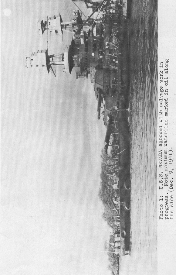
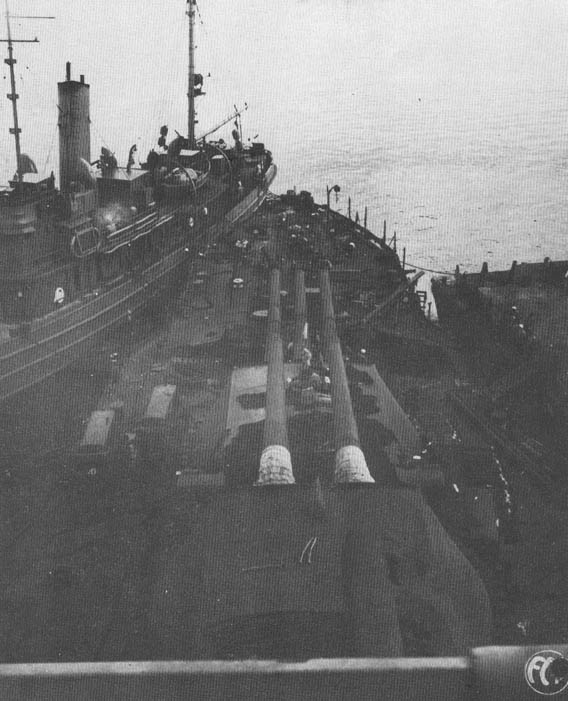
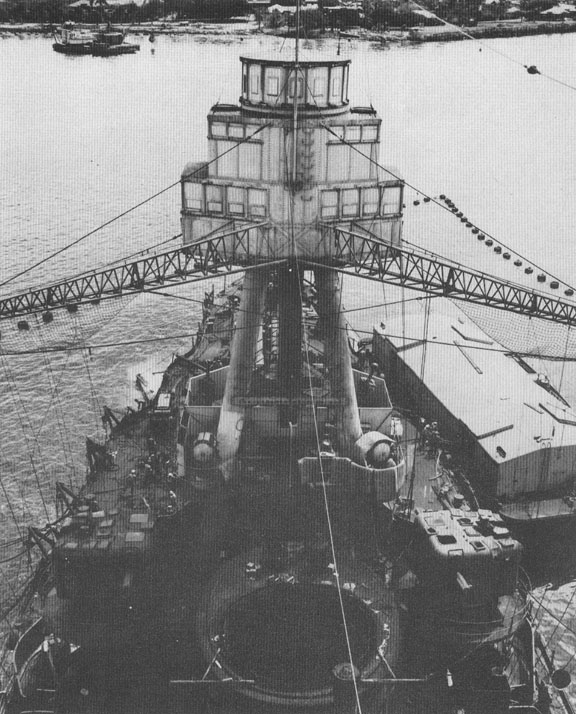
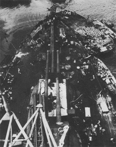
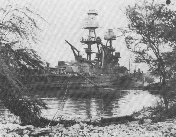
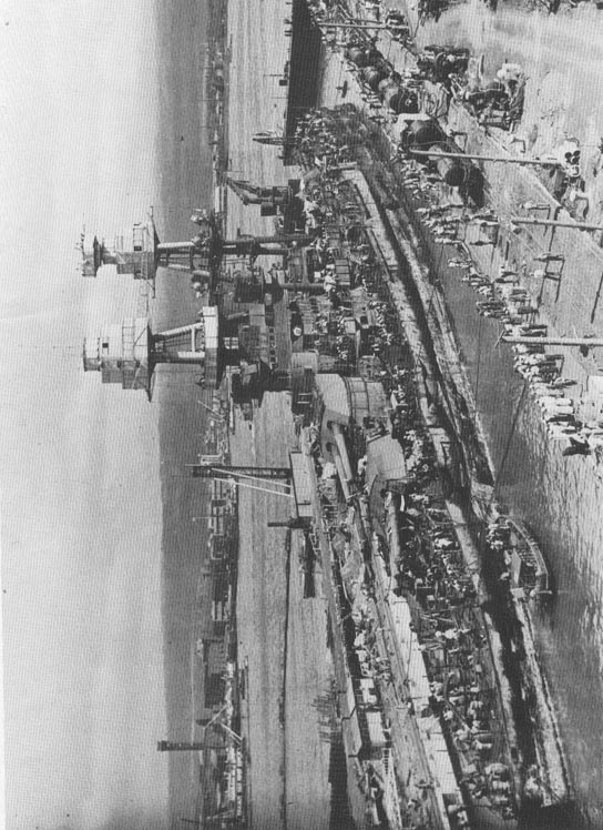
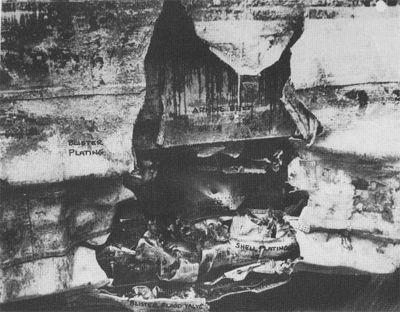
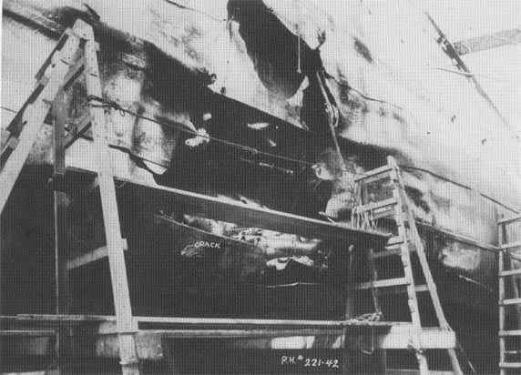
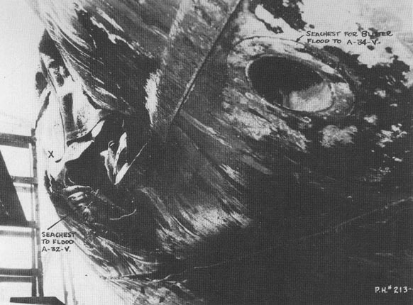

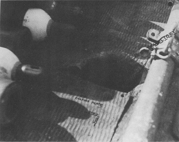
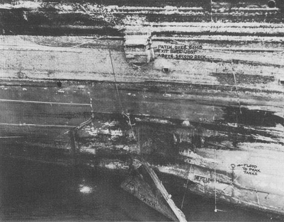
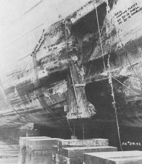
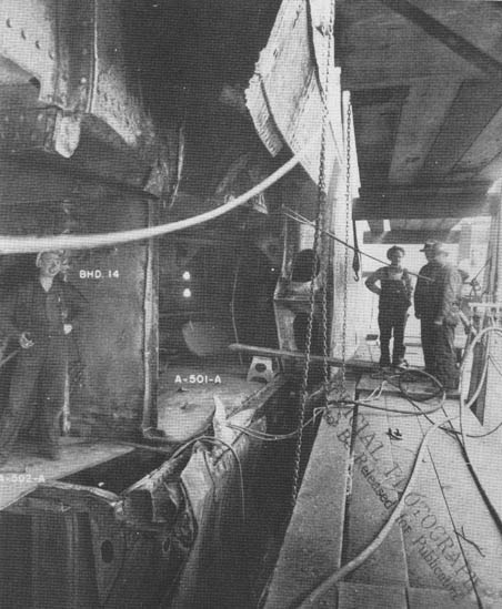
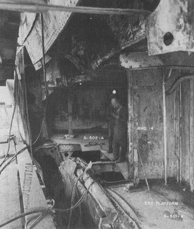
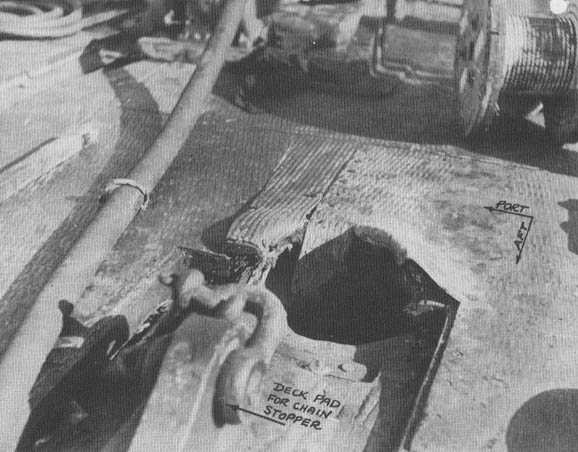
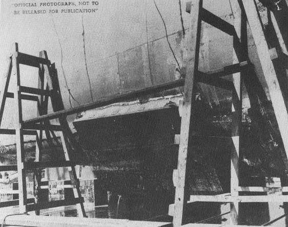
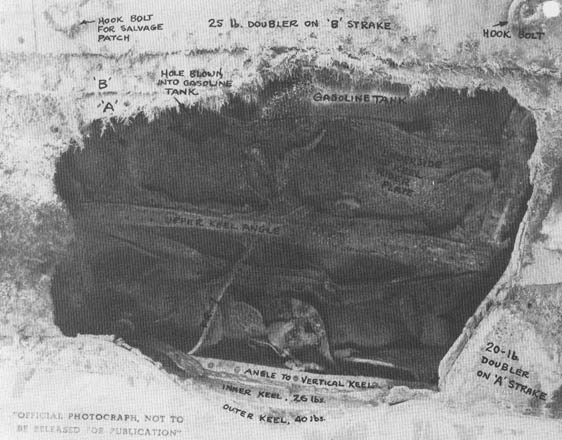
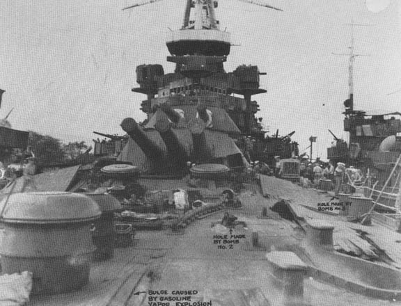
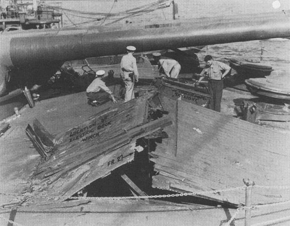
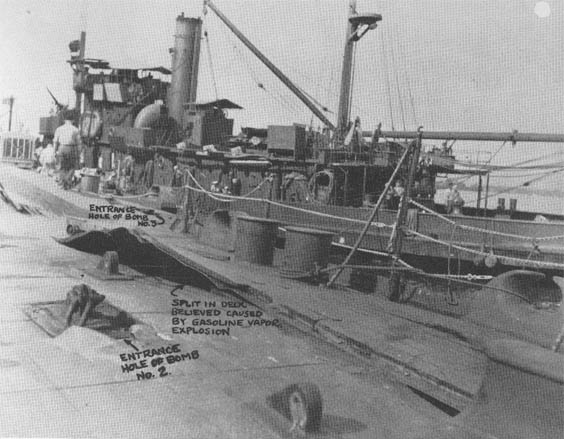
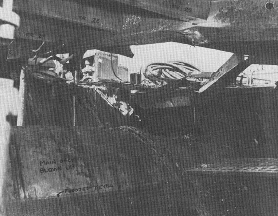
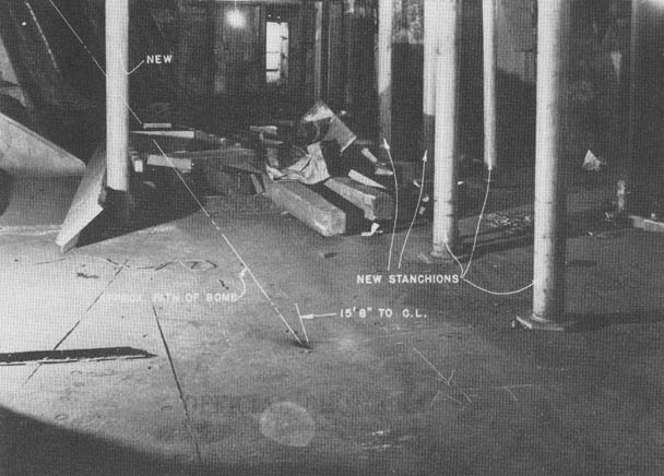
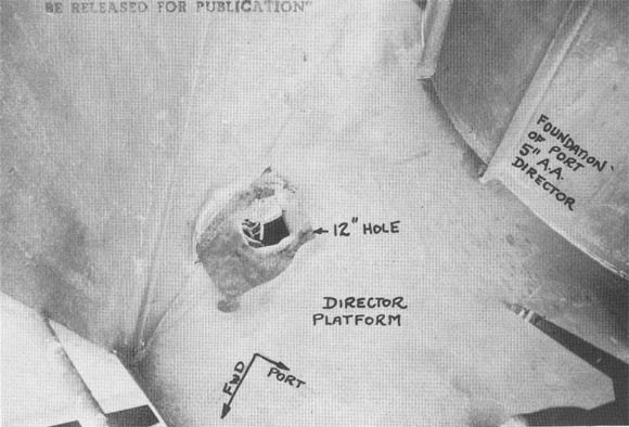
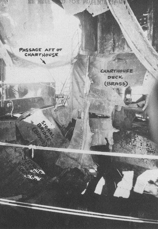
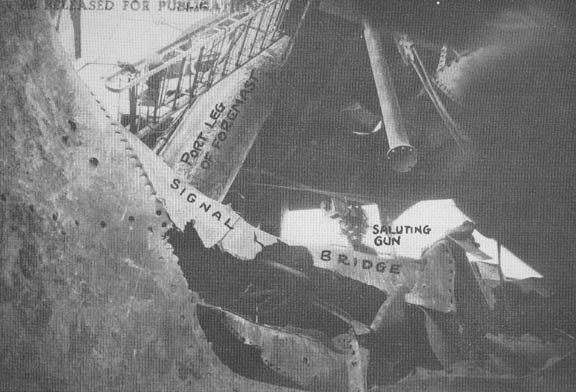
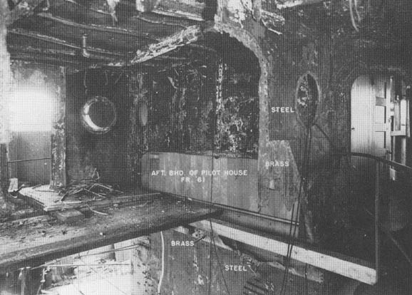
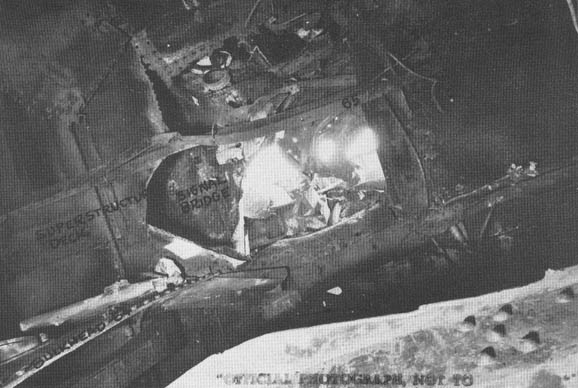

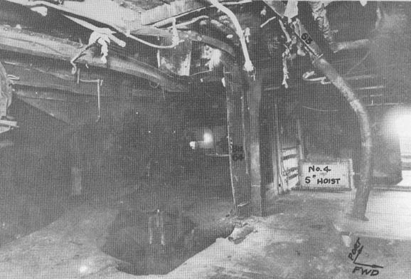
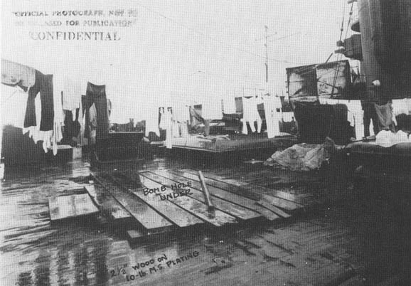
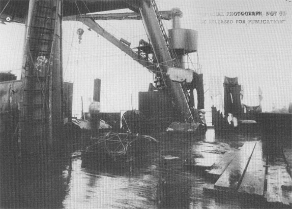
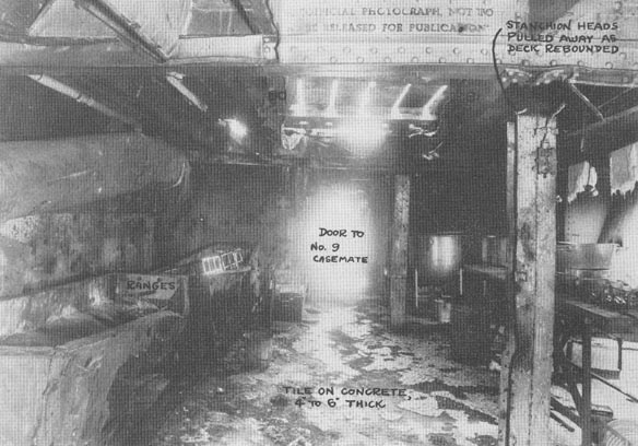
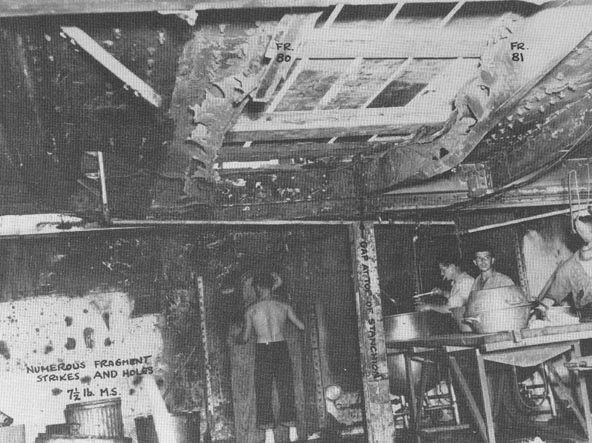
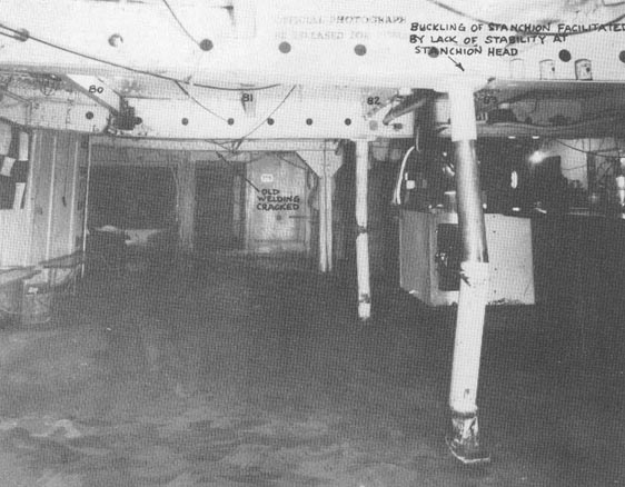
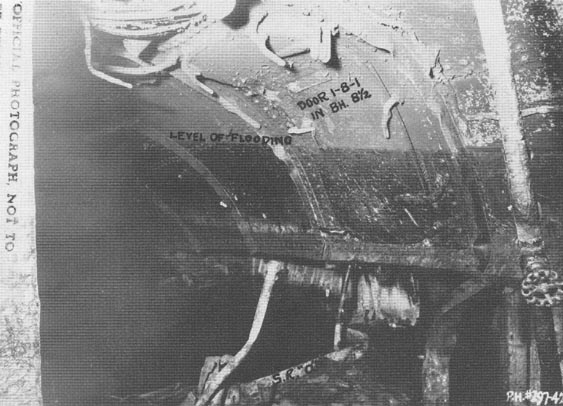
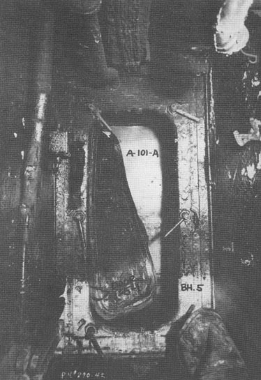
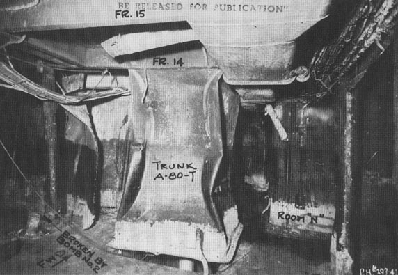
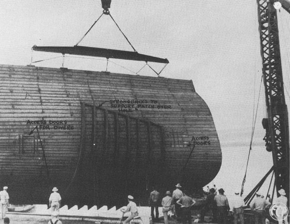
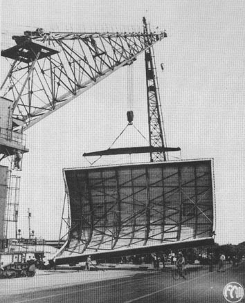
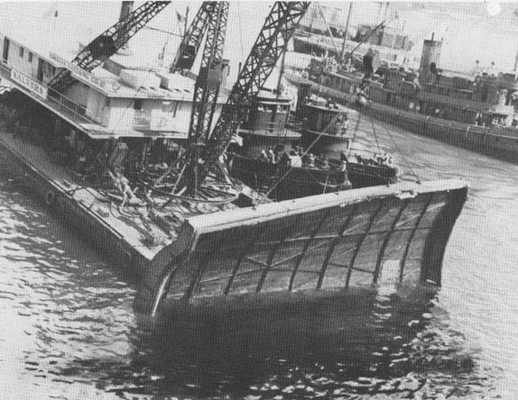
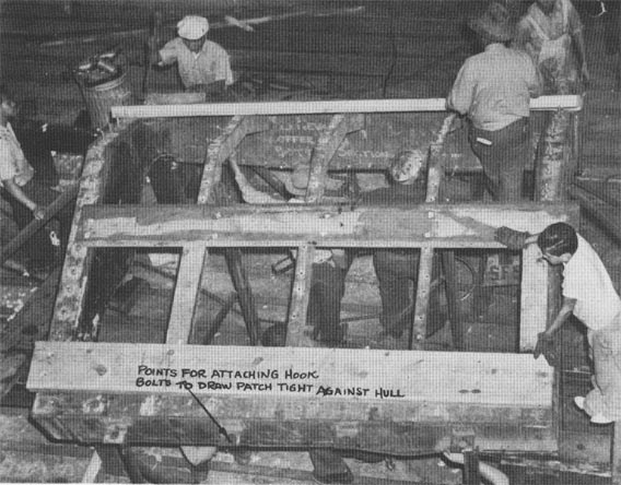
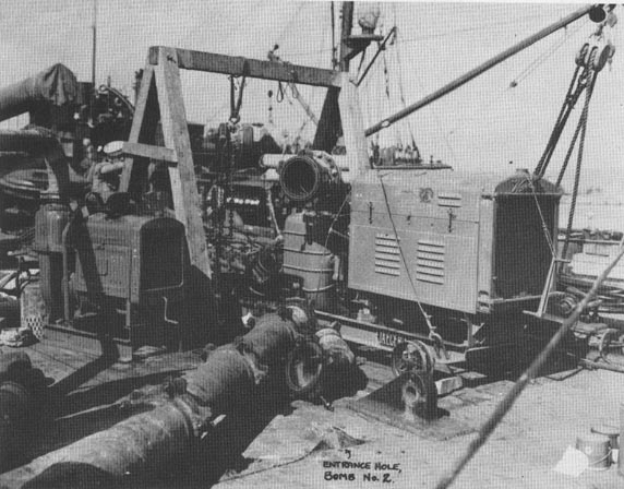
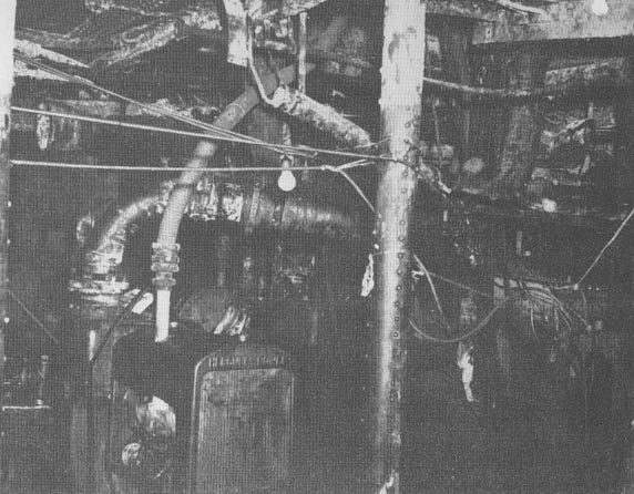
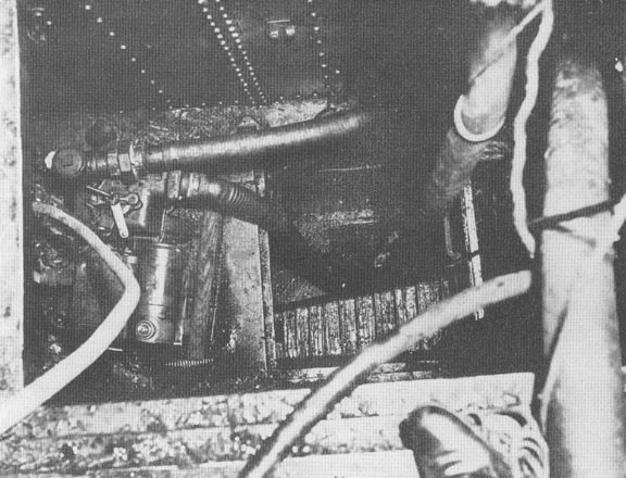
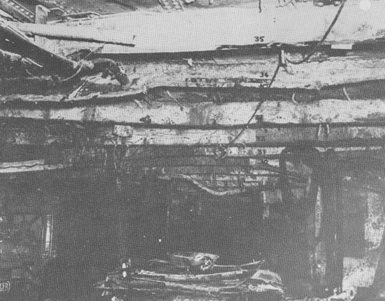
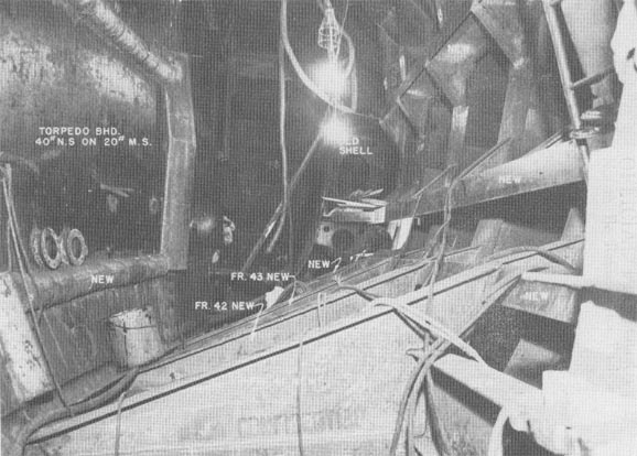
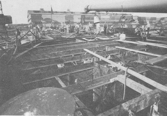
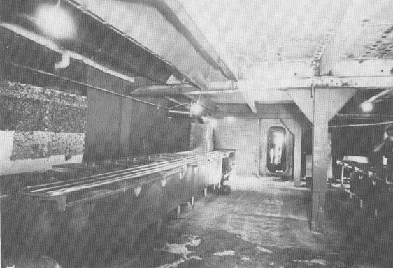
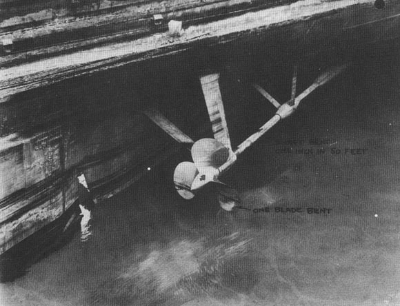
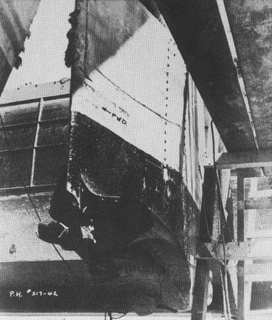


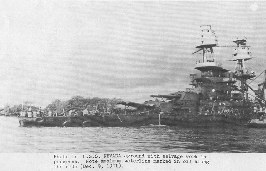