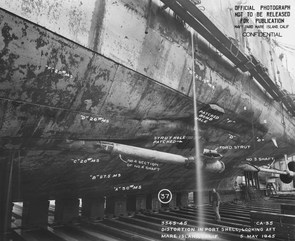
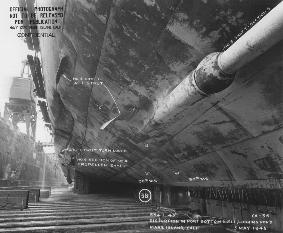
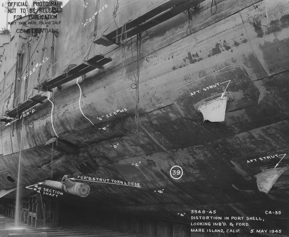
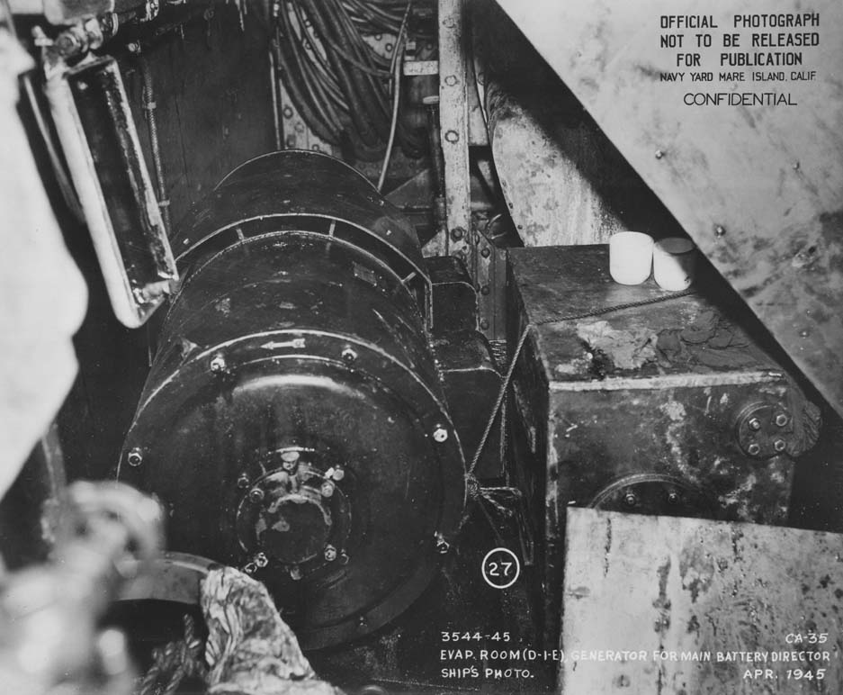
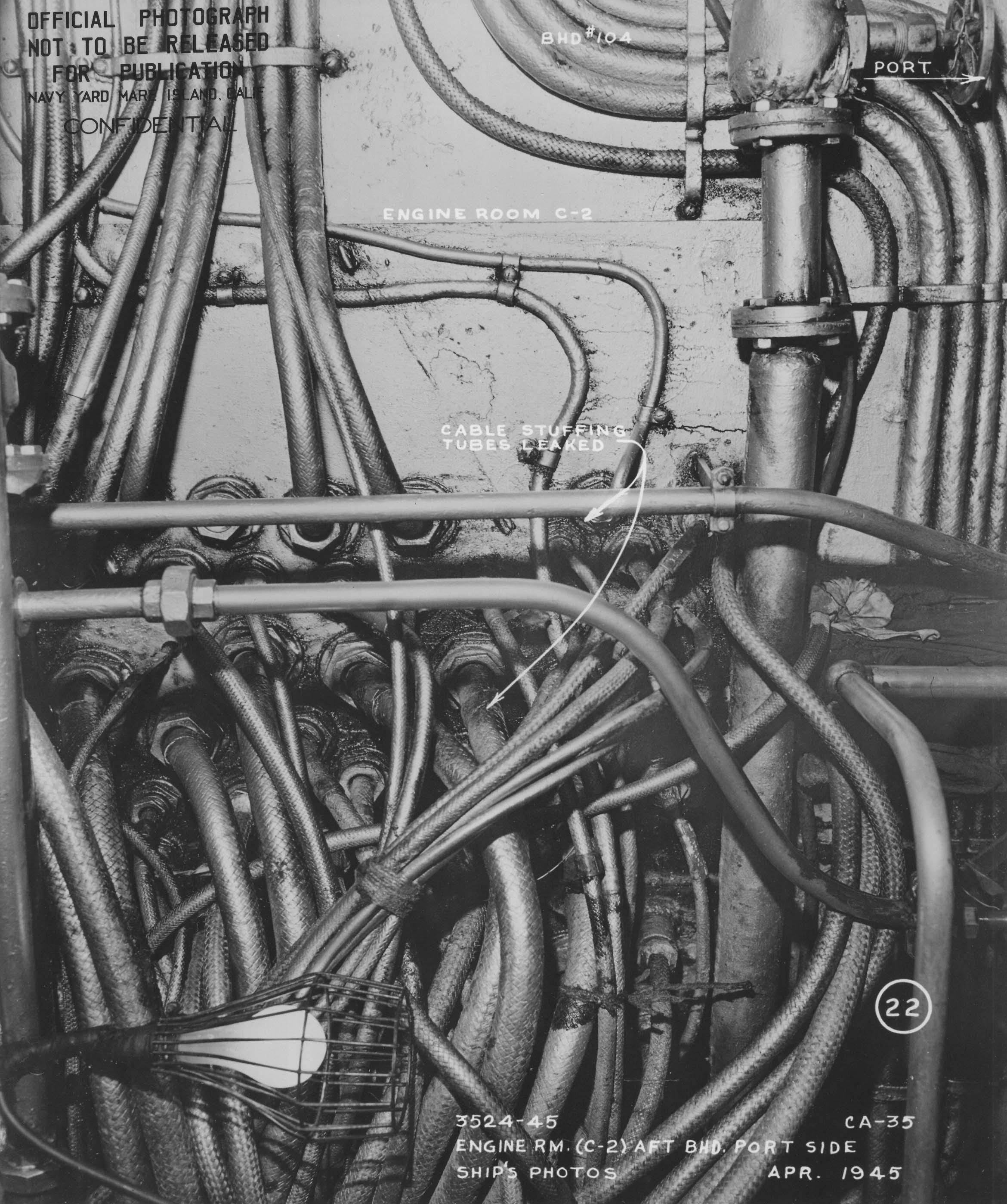
Damage Plate I
Click to enlarge

Click to enlarge

Damage Plate II
Click to enlarge

Click to enlarge

If you can see this text here you should update to a newer web browser
Normal | Highlight & Comment Highlighted Text are in Yellow
|
CONFIDENTIAL Aug-7'45 U.S.S. INDIANAPOLIS (CA35) REPORT OF WAR DAMAGE OKINAWA 31 MARCH 1945
PREPARED BY NAVY YARD, MARE ISLAND |
|
U.S.S. INDIANAPOLIS (CA35) PLANE CRASH AND BOMB DAMAGE
CONTENTS SECTOR
SKETCH OF DAMAGE Plate No. 1. Port and Starboard Profiles and Cross-Section. PHOTOGRAPHS OF DAMAGE Photo No.
- 2 -
|
||||||||||||||||||||||||||||||||||
|
Missing Page
|
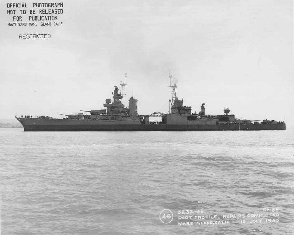
SECTION I - FORWARD 1. This report has been prepared in compliance with reference (b), to supplement the information in reference (a) with a complete and detailed description of damage as disclosed from an inspection of INDIANAPOLIS upon her arrival at Mare Island. Photographs and sketches prepared by Navy Yard, Mare Island are included to assist in the description of the damage. 2. After temporary repairs by forces afloat in the South Pacific, INDIANAPOLIS proceeded to Navy Yard, Mare Island, arriving 3 May 1945. She was placed back in service on 13 July 1945 with all battle damage repaired and authorized alterations completed. SECTION II - GENERAL
- 4 - |
|
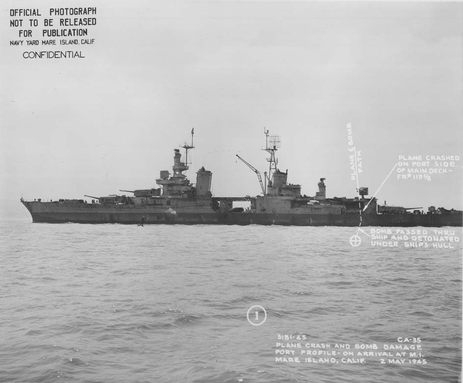
NARRATIVE 4. On 31 March 1945, INDIANAPOLIS was in column astern the SALT LAKE CITY, distance about 1000 yards, closing to take station 600 yards astern SALT LAKE CITY. Condition I was set in the AA battery. At 0706, a single enemy fighter plane, an "Oscar," was sighted emerging from a low overhanging cloud in an almost vertical dive slightly on the starboard side of the ship. The plane was apparently headed for the ship in a suicide dive, probably aimed at the bridge. Eight 20mm guns were brought into action, but the time was so short that only five of them had time to empty their magazines before the plane crashed on the port side of the main deck aft, at frame 112 - 113, at the edge of the waterway. The plane probably was out of control before it struck, as tracers were seen to enter the plane. Just before striking the main deck, the plane's left wing tip struck the floater net rack on the splinter shield of the aft 20mm gun platform and this shock probably caused the bomb or bombs to release. The bomb causing the major damage pierced the main deck plating before the plane struck. Measurements indicated that this bomb probably was carried under the planes left wing. It is possible that there was a second bomb under the planes right wing, as several witnesses reported hearing a second explosion. If this was the case, it is probable that the second bomb was released at the same time as the first and went harmlessly over the side. Immediately after the plane crashed on the deck, it toppled overboard into the sea and there was a deadened sound as the bomb or bombs exploded. A column of oil and water shot up through the deck and covered the main deck aft with a layer of fuel oil, sea water and some gasoline from the plane's tanks. Fortunately there was no fire, but the ruptured compartments flooded almost immediately. The ship soon reached its maximum draft and list, and inspection revealed the water-tight boundaries of the damaged area to be holding. With the flooding controlled it was decided there was no immediate danger and the ship proceeded to Kerama Retto where emergency repairs were made by USS CLAMP (ARS33). 5. Immediate consequence of damage on the ship's fighting efficiency:
|
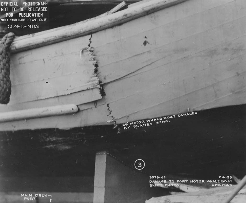
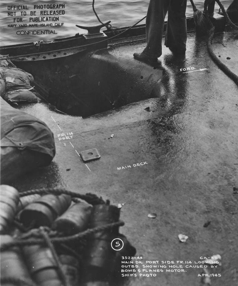
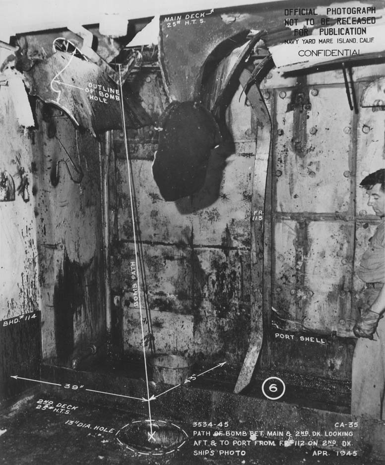
SECTION III - PLANE CRASH AND BOMB DAMAGE 6. The major damage sustained by INDIANAPOLIS resulted from a bomb explosion outside the hull of the ship on the port side, after the bomb had pierced the entire ship's structure. Minor damage was caused by the plane crashing on the port edge of the main deck and by the bomb's passage through the ship's structure, before the delayed action fuze caused it to explode. A description of the damage to the ship's structure and equipment follows: A. STRUCTURAL DAMAGE AND FLOODING 7. The plane's left wing tip struck the floater net rack on the port splinter shield of the after 20mm gun platform, damaging the forward end of the rack (photo 2). This slight impact probably released the one or more bombs carried by the plane and also oaused the plane to pivot about this point and crash just inboard of the port waterway (Plate I). Wreckage of the plane toppled overboard immediately. The planes motor tore a hole approximately four by five feet in the 25 lb. HTS main deck plating between frames 112 and 114 (photos 4 & 5). A four foot section of main deck longitudinal No. 8 was destroyed. Although the major portion of the plane's wreckage went overboard, parts of the motor and propeller were found in compartment D-201-L, under the hole in the main deck. The plane's left wing struck the port 26 foot motor whale boat, which was stowed on the main deck, partially destroying it (photo 5). 8. The plane's port bomb, estimated to have been a 500 lb., AP, delayed-action fuze type bomb, pierced the main deck at the same place as the plane's motor. From photo 6 it is apparent that the bomb penetrated the main deck before the plane's engine struck, as the bomb hole may be seen in the plating which was subsequently ruptured by the engine. The bomb passed through the 25 lb. HTS main deck plating and entered compartment D-201-L, crew's quarters, destroying a diving gear - 6 -
|
||||||||||||||||||||||||||||
|
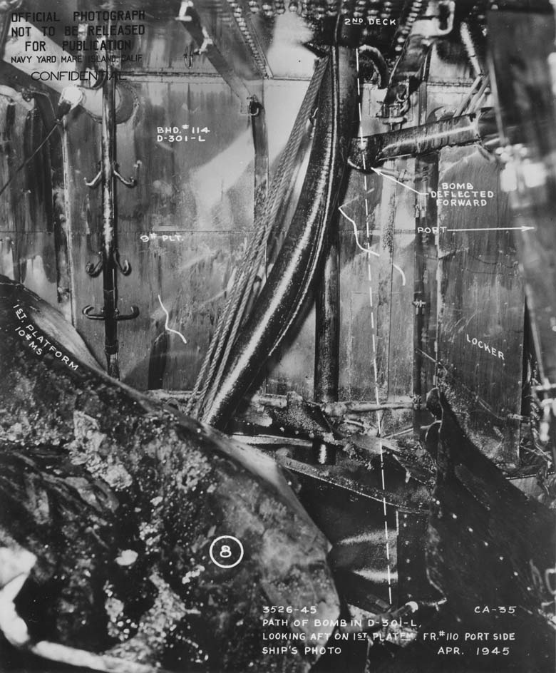
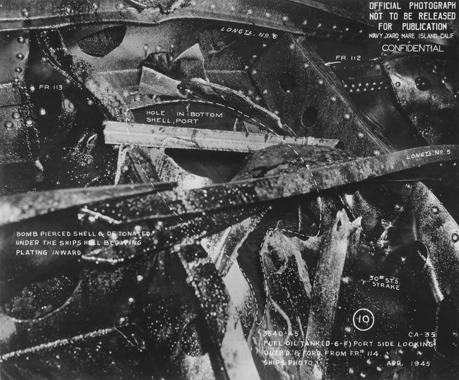
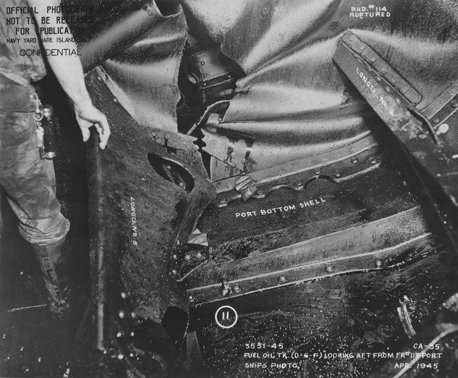
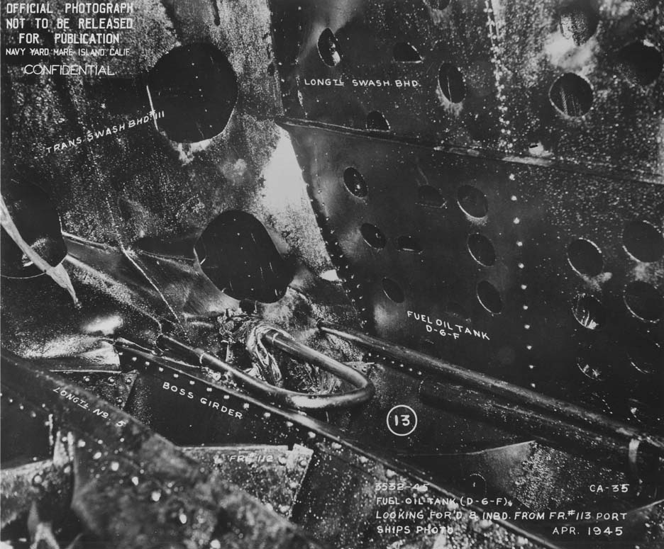
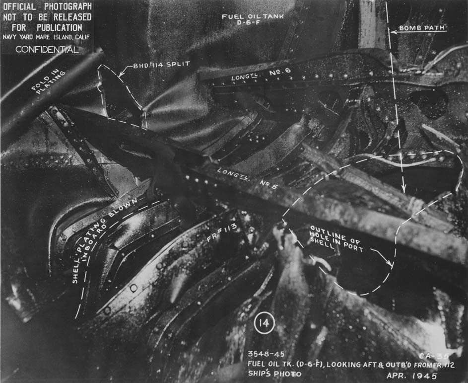
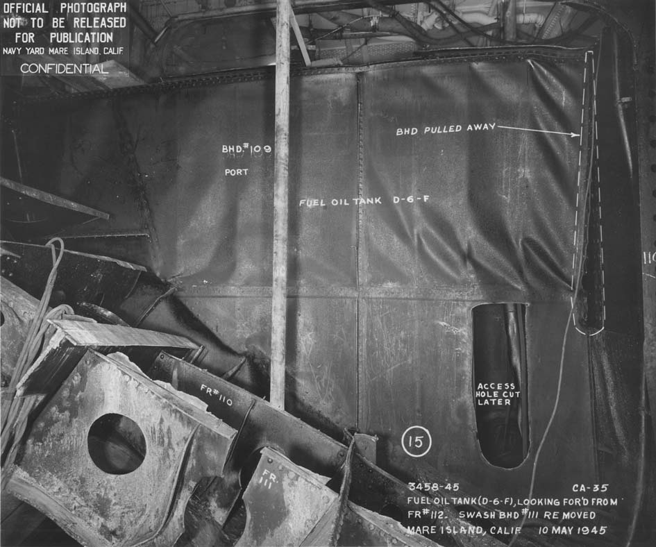
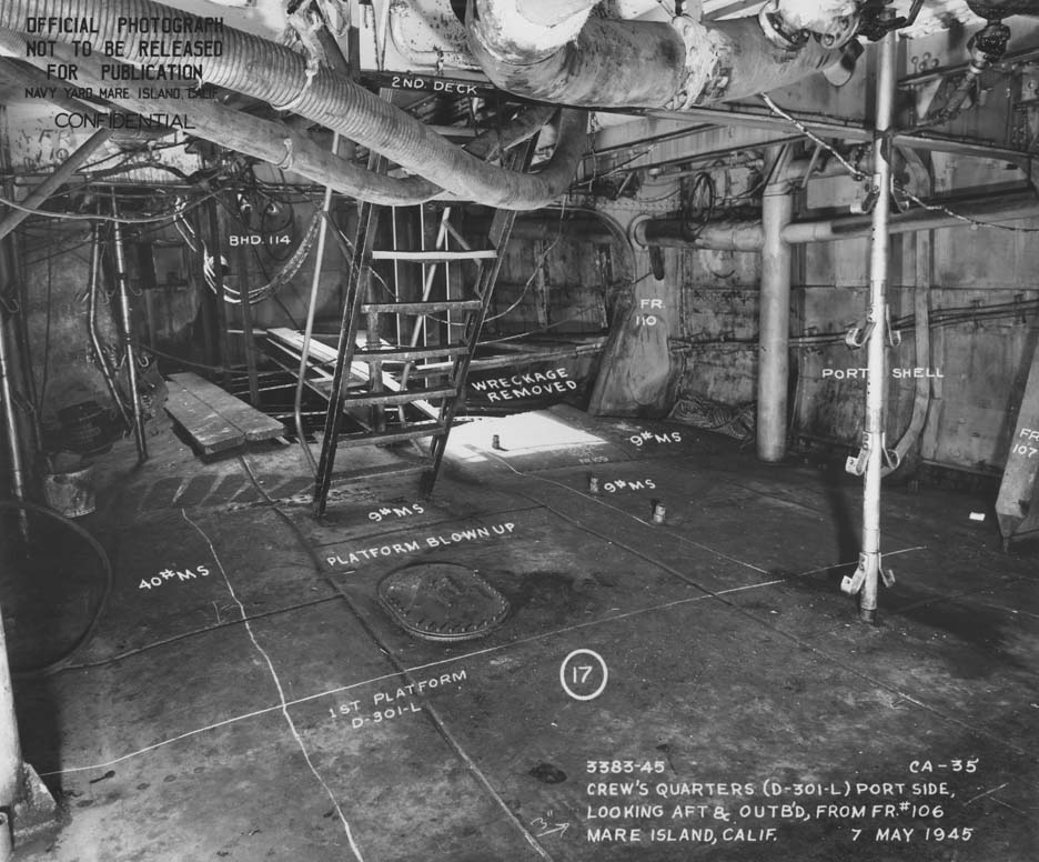
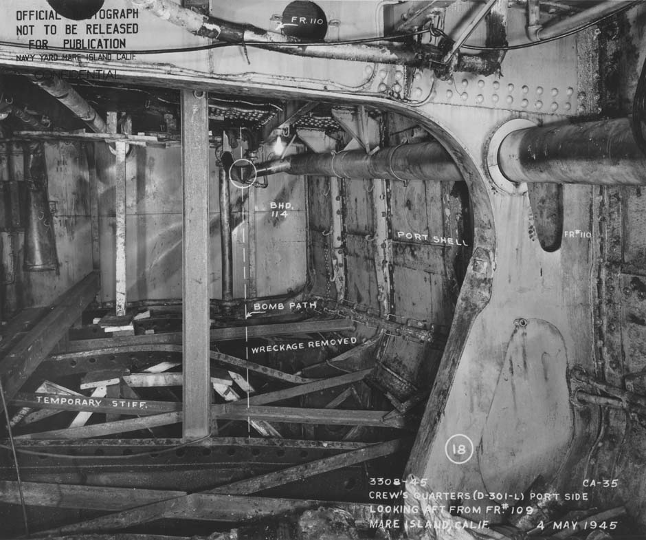
locker (photo 6). The bomb then pierced the 25 lb. HTS second deck plating, 39" forward of bulkhead 114 and 43" inboard of the ship's shell, making a circular hole about 13" in diameter, and entered crew's mess, D-3OI-L (photo 7). Beneath the second deck the bomb struck a 5" fuel oil overboard discharge line, damaging the line (photo 7) and deflecting the bomb forward. The bomb continued through D-301-L, pierced the 9 lb. MS first platform deck, entered fuel oil tank D-6-F, passed through this tank and out through the 30 lb. MS plating of "F" strake at frame 112. As the bomb cleared the ship, the delayed-action fuze finally took effect and detonation occurred just outside of the shell plating. 9. The effect of the underwater detonation of the bomb was that of a small torpedo. Much of the force of the explosion was transmitted back into the ship through the hole from which the bomb had emerged, blowing the edges of the bomb hole inward and increasing the size of the hole to approximately four by five feet (photos 10 & 14) . D-6-F was 95% filled at the time, and the force transmitted by this oil burst all the watertight boundaries of the tank (photo 9, 11, 12, 14 & 15). Fuel oil tank D-4-F was 95% full, D-2-F and D-8-F were 100% full, and these tanks were all flooded when the force of the explosion was transmitted from D-6-F, rupturing the oiltight bulkheads of these tanks. All swash bulkheads in the tanks were buckled. The after bulkhead (118) of fuel oil tank D-8-F was ruptured, completely flooding D-10-A, provision storeroom. The evaporator room, D-l-E, was completely flooded as a result of the rupture of it's port longitudinal bulkhead beneath the armored section. D-4O2-V was also flooded when the port longitudinal bulkhead of this space was split. The tops of D-902-F and D-9O4-F were forced up, rendering the No. 1 evaporator set inoperative. Salt water piping leaks occurred in D-501-M, D-502-E and D-905-V but these were not serious. There were very minor leaks in the port side of bulkhead 104 which allowed about 6 inches of flooding in the after engine room, C-2. Similarly there were small seepage leaks into D-12-A, provision storeroom, through sprung rivets in the port side of bulkhead 123. Leakage through cable stuffing tubes in both the forward and after bulkheads of the evaporator room added to the slow flooding of the after engine room and the after gyro room. There was also slow leakage through No. 4 shaft stuffing tube. 10. The force of the explosion tore the forward strut of No. 4 propeller shaft from the ship, leaving a second hole in "D" strake, two by five feet, at frame 113. The area of serious indentation of the hull extended from frames 104 to 122, and from the keel to within 15 feet of the main deck, (photos 37, 38, 39, 40). - 7 -
|
|
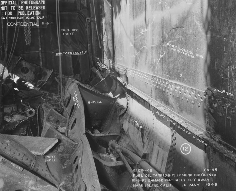
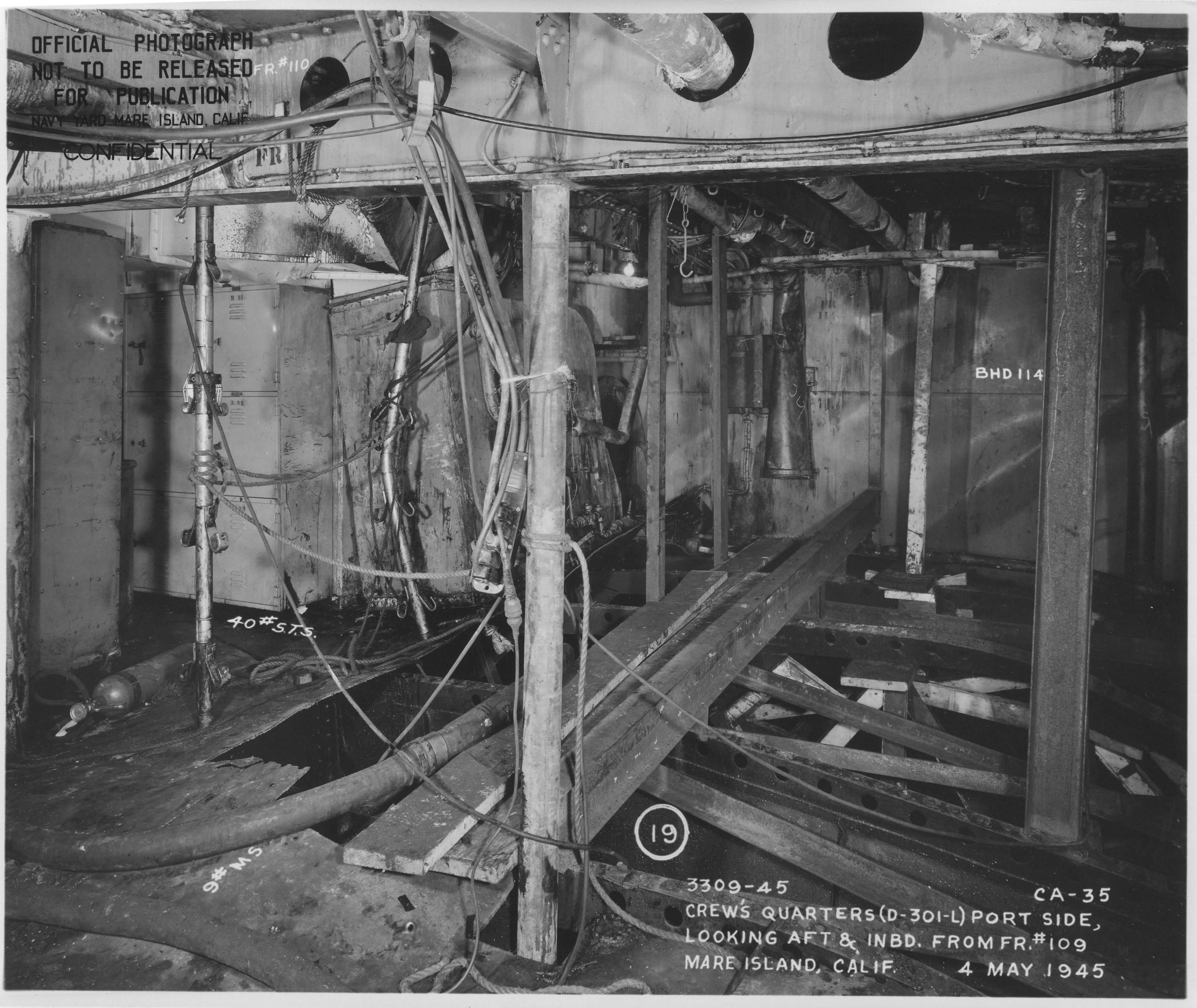
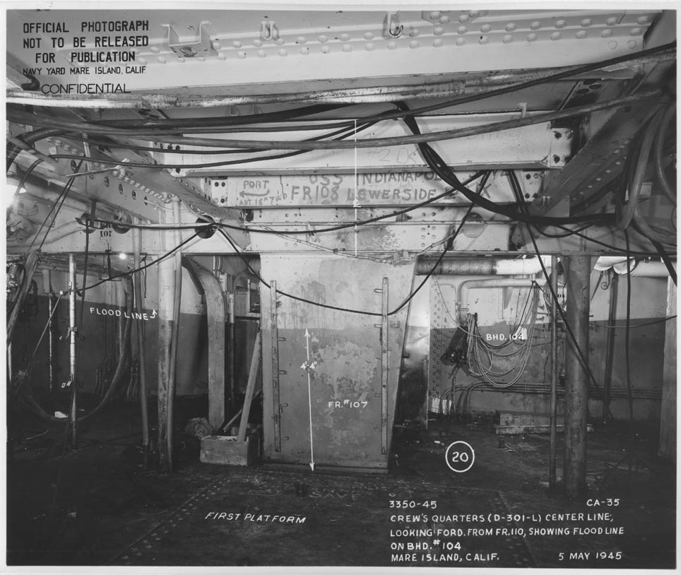
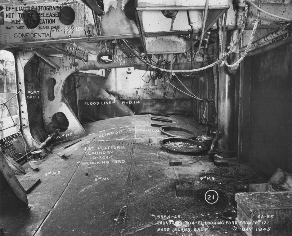
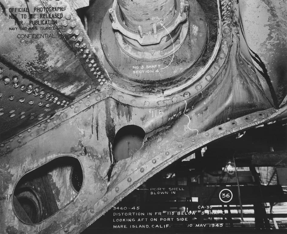
11. The force of the explosion forced sea water and oil in D-6-F upward and outward, rupturing the 9 lb. MS first platform deck on the aft port side of D-30l-L and blowing the plating up a maximum of four feet between frame 108 and ll4, extending inboard about 16 feet (photos 8 & 9). Compartment D-301-L flooded to the external waterline, a depth of about 4 feet in the compartment (photo 20). The oil in D-8-F transmitted sufficient force to bulge the first platform a maximum of 18 inches at frame 115, in the laundry (photo 21). The plating pulled away from the deck beams without rupturing, but leaving rivet holes through which the laundry flooded to the external waterline. 12. The following is a summary of the flooded compartments:
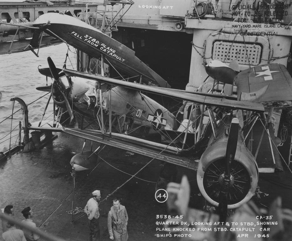
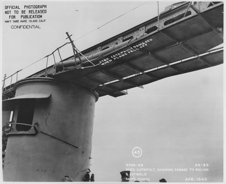
Submersible pumps were used to control the slow flooding, as some of the ship's drainage lines were ruptured. 13. General flexure of the ship was noted. No important damage resulted to the ship's structure, but all three ship's airplanes were damaged by shock. The starboard airplane was knocked off its catapult to the quarter deck and the port plane was knocked askew on its catapult, badly damaging both planes. The third plane, which was parked on the quarter deck; on the ship's centerline, was damaged when the starboard plane fell on it (photo 44). Both catapults were damaged. The starboard catapult had the outboard and inboard catwalk distorted and life lines and stanchions in the amidships section bent and torn away (photo 45). The port catapult also had life lines and stanchions damaged. After minor repairs by the ship's force, both catapults were put back in operation. The whip of the foremast damaged some radar equipment, and spring bearings and No. 2 HP air compressor suffered shock damage. 14. From April 1 to 7 the INDIANAPOLIS was given temporary repairs by CLAMP (ARS33). Patches were welded on the main deck, blown up plating on the first platform was cut away and temporary stiffeners were installed. Soft patches were placed over the holes In the hull by divers and concrete was poured in the interior. INDIANAPOLIS patched the bomb hole in the second deck with it's own velocity power tool. Later INDIANAPOLIS - 8 -
|
|||||||||||||||||||||||||||
|
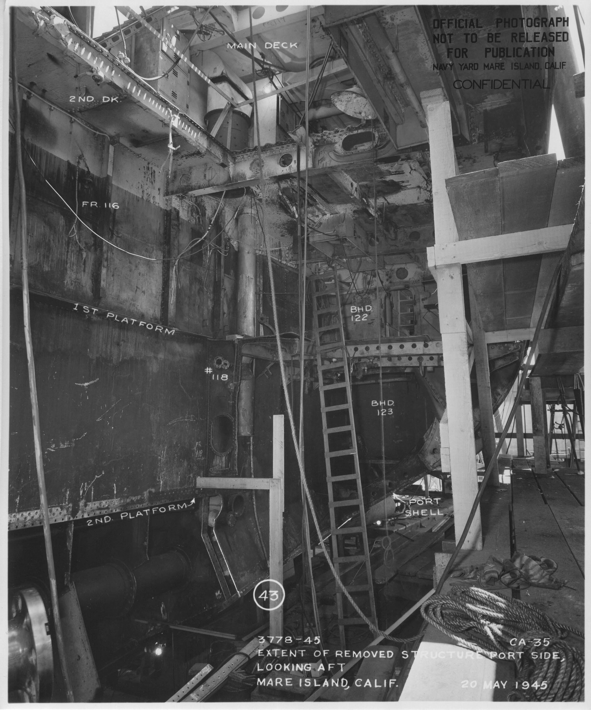
proceeded to Guam where repair forces chipped out the concrete and removed soft patches with the intent of replacing them with steel plate, but this was found to be impractical and the soft patches and concrete were replaced. Soon after, INDIANAPOLIS proceeded to Navy Yard, Mare Island for permanent repairs. 15. The following summary of hull structure replaced during the currant repair is presented as a measure of the extent of damage (photos 42 and 43) .
Bulkheads
All shell and deek frames, and longitudinals in the damaged area were also replaced. - 9 -
|
||||||||||||||||||||||||||||||||||||||||||||||||||||||||||||||||||||||||||||||||||||||||||||||||||||||||||||||||||||||||||||||||||||||||||||||||
|
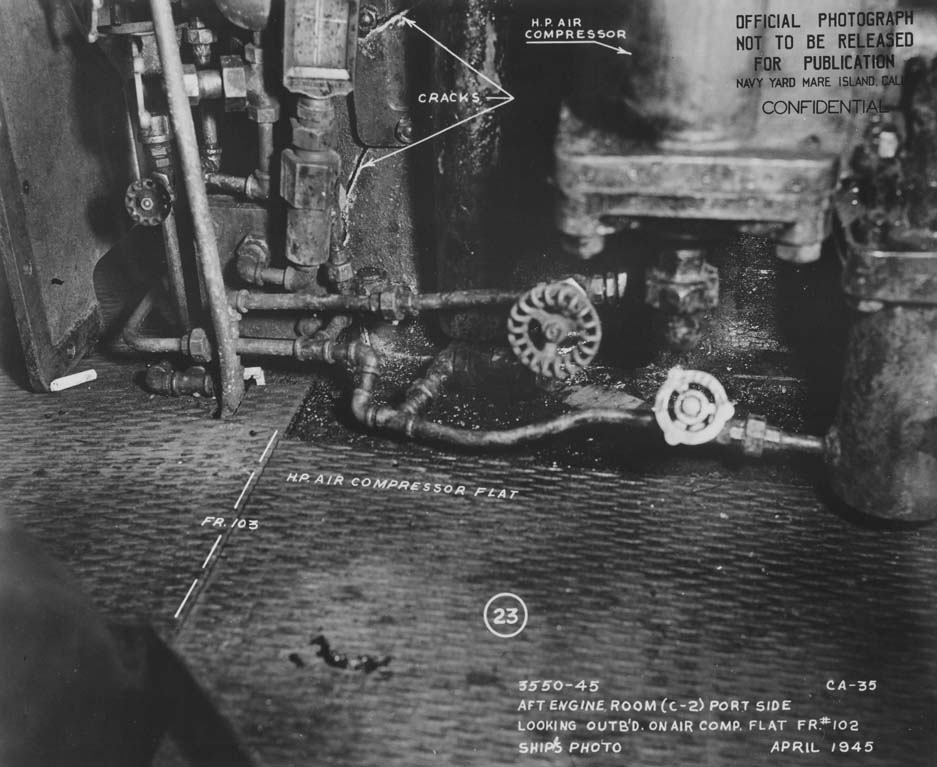
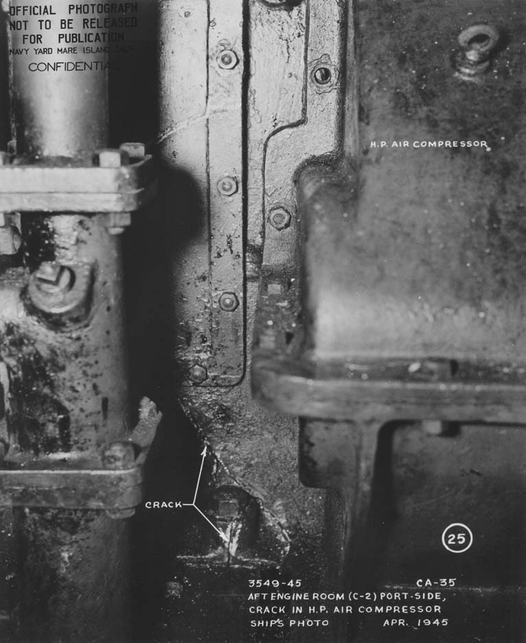
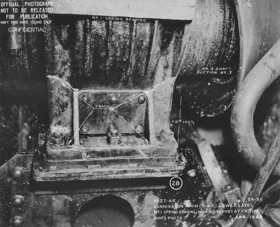
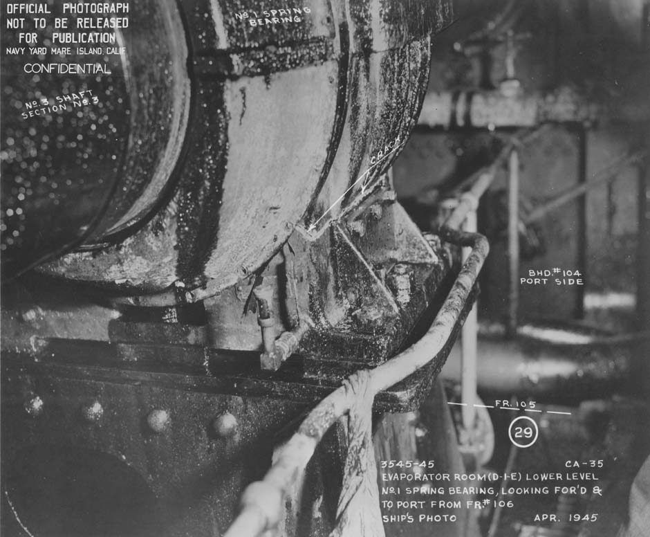
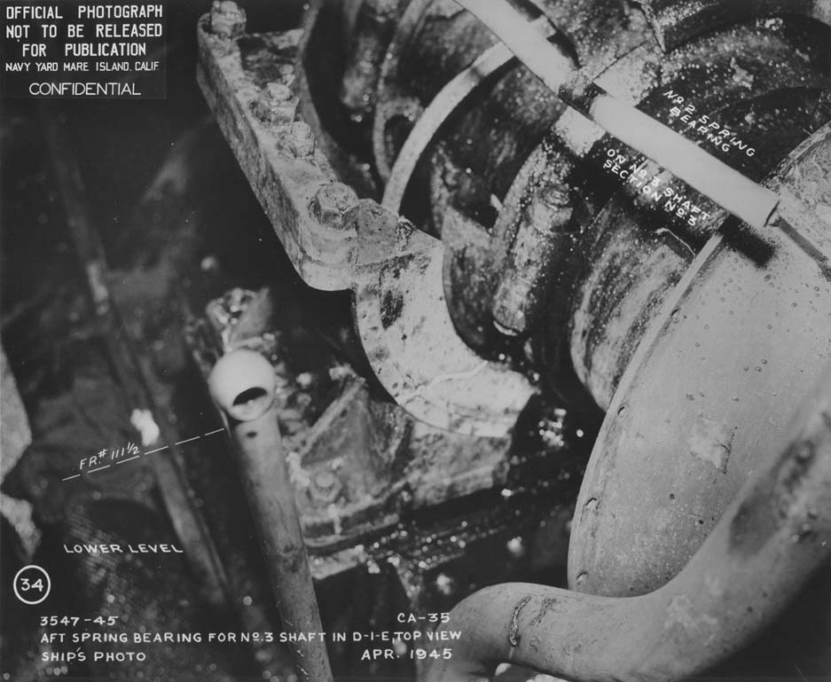
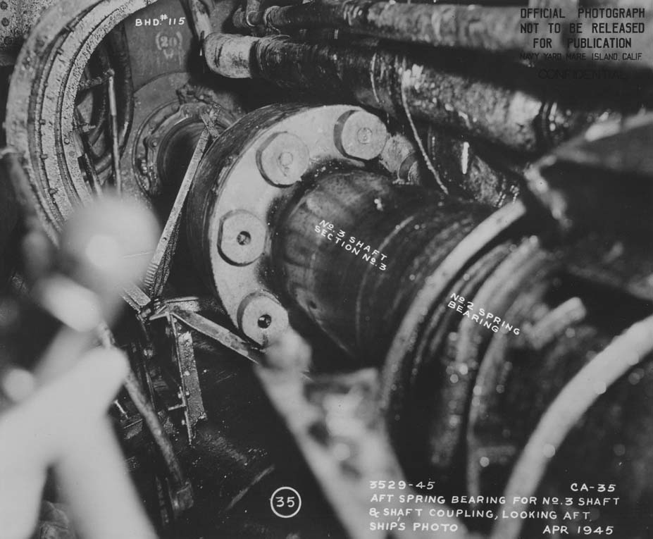
16. Ref (a) recommended that watertight trunks to the evaporator room and gyro aft be extended so that access to these compartments would be from the second deck rather than from the first platform. The evaporator trunk was extended during the current repair, but excessive interference with piping and cables prohibited the extension of the trunk to gyro aft. MACHINERY DAMAGE 17. The bomb exploded outboard of No. 4 shaft forward strut, after passing through the ship. The force of the explosion ruptured the coupling between No. 4 and No. 5 sections of No. 4 shaft by pulling the tapered ends of the bolts through the tapered holes in No. 4. section coupling. The forward strut for No. 4 shaft was torn loose at the hull (photos 37, 39, and 40), and the outboard arm of the after strut was ruptured (photos 37, 38, 39 and 41). No. 4 turbine started to over-speed immediately after the hit and was secured. 18. During the temporary repair period, the after strut was cut away completely (photo 41). While attempting to salvage No. 5 section of No. 4 shaft, the wire slings carried away and the shaft, propeller and strut were lost. All the remaining sections of No. 4 shaft were slightly bent and the shaft was 3/16 inch high at the stern tube. Photo 37 is misleading as it shows No. 4 section bent considerably, but the forward coupling had been disconnected and the weight of the cantilevered shaft and strut had sprung the stern tube bearing. 19. No. 3 shaft was kept in operation for approximately two hours after the hit. When the evaporator room was pumped out, both spring bearings on this shaft were found to be cracked and pulled away from their foundations (photos 28, 29 and 34). No. 3 shaft was not used again and when examined at this Yard, Nos. 3, 4 and 5 sections were found to be slightly bent. The shaft was misaligned 1 1/4 inches to port and 13/32 inch low at the after strut. Nos. 1 and 2 shafts were in continuous operation until INDIANAPOLIS reached this Yard and upon examination were found to be only slightly misaligned. 20. The cast iron frame of No. 2 HP air compressor, located in the after engine room, was badly cracked and is being replaced (photos 23-25). The only damage suffered by equipment In the evaporator room was due to corrosion, occasioned by the flooding of the compartment. The equipment was removed, cleaned and overhauled and re-installed during the current repair period. - 10 -
|
|
C. ELECTRICAL DAMAGE. 21. The 6000 CPM vent blower in crew's mesas D-301-L, was demolished although the motor is repairable. In the laundry, D-3O4-E, extreme distortion of the deck and of bulkhead 114 damaged several motors and controllers and all were oil soaked. All equipment in the evaporator room was oil soaked. The compartment was flooded with oil and sea water from ruptured fuel oil tank D-6-F, but the oil entered the compartment before the water and thoroughly covered all equipment. Megger tests on many cables in the compartment gave infinity readings when tested at Mare Island. Others gave low readings and these are being replaced. The degaussing and after main battery director motor-generator sets and controllers were oil soaked, but repairable. The meters on the control panels for the director motor-generator set were stuck at half scale, possibly from thick oil in the movements. The rears on the shaft revolution transmitters for No. 2 and No. 5 shafts were damaged, and the transmitters were filled with water. The meters on the salinity indicator panel were damaged beyond repair. 22. Oil and water, spurting through the stuffing tube area between the evaporator room and the after engine room, thoroughly wet the turning motor controllers for shafts No. 2 and No. 3 and the motor on the lubricating oil purifier. These units were mounted below and several feet forward of the stuffing tube area. 23. In the after gyro room, D-502-E, the compass bowl suspension springs elongated or broke, dropping the compass and spilling the mercury. About three days later the compass was repaired and replaced in operation, but only to determine whether or not it would fall due to possible internal damage. Even though it operated with only 30' error when on a straight course, the compass was not used to supply gyro inputs. The forward gyro was used to supply the after gyro signal circuits by closing the tie between the forward and after gyro switchboards. Even with the tie closed, the equipment taking gyro supply from the after gyro switchboard could not be used, as the 110 volt A.C. supply for the synchros comes from the auxiliary I.C. switchboard In the after gyro room, and this switchboard, although undamaged, was secured for about three days as a precaution against fire. As soon as the after gyro room was cleaned and exhausted of oil and vapor, the auxiliary I.C. switchboard was energised by closing the tie to the main I.C. switchboard. - 11 -
|
|
24. Water, flowing through loose packing in the stuffing tube area between the evaporator room and the after gyro room, thoroughly sprayed the 50 KVA motor-generator set for the auxiliary I.C. switchboard and partly sprayed the fire control switchboard and the gyro-compass. The fire control switchboard and the motor-generator set were secured and left secured. 25. Tubes were broken in the after SK, SG, and Mk. 8 radar units by shook from the explosion. The shock also tripped the overload relays on the SK and SG transmitters. The relays were quickly reset to place the transmitters back in operation. Damage and oil flooding in the after gyro room cut out the gyro inputs to the radars and placed them on a relative basis until the gyro room was cleared as explained previously. 26. The bomb explosion caused the foremast to whip, breaking the TDY antenna pedestal casting, cracking five reflector rods and rupturing the joint on the coaxial line. Temporary repairs were made two days later. The shock also spilled mercury from the forward Mk. 8, Mod 3A gyro compass. This compass has a splash retarding ring on the mercury tank designed to prevent excessive spilling and splashing of the mercury. Additional mercury was added to the compass as necessary for its proper operation. 27. The progressive flooding through cable stuffing tubes experienced by INDIANAPOLIS was not of serious consequence, as power was available to remove the flooding water by pumping. However the condition of cable stuffing tubes is such that they constitute a serious reduction in the ships ability to survive more serious damage. It was reported that liquid from the evaporator room spurted five feet into the after engine room through stuffing tubes in both the port and starboard wireways. Similar leakage into gyro aft occurred through starboard wireway stuffing tubes. An examination in this Yard revealed many stuffing tubes throughout the ship where the gland nut was pulled up tight against the stuffing tube, permitting no further tightening without the addition of packing rings.
- 12 -
|
|
Damage Plate I
Click to enlarge Damage Plate II
Click to enlarge
|
SOURCE:
Transcribed by RESEARCHER @ LARGE. Formatting & Comments Copyright R@L.