|
RESTRICTED
| Ship: |
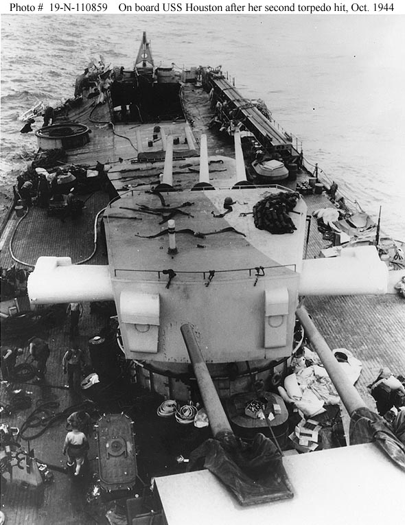
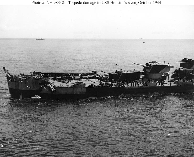
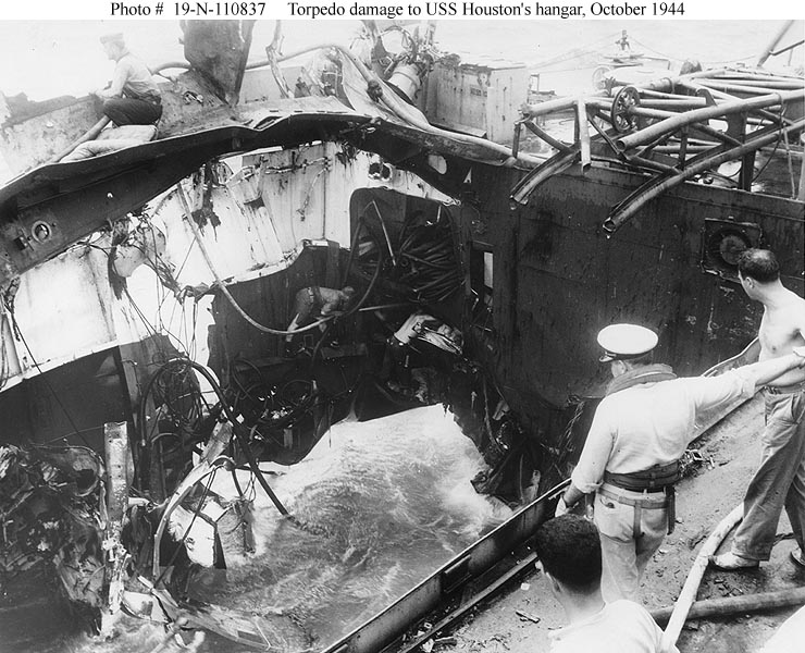
USS HOUSTON (CL 81) |
| Cause of Damage: |
2 Torpedoes |
| Date: |
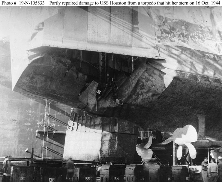
14 and 16 October 1944 |
| Place: |
Off Formosa |
| Class: |
CLEVELAND (CL 55) |
| Standard Displacement: |
10,000 tons |
| Length Overall: |
610' 0" |
| Extreme Beam: |
66' 4" |
| Draft Before Damage: |
24' 1-1/2" |
| Launched: |
19 June 1943 |
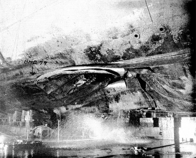
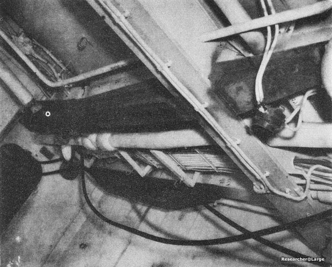
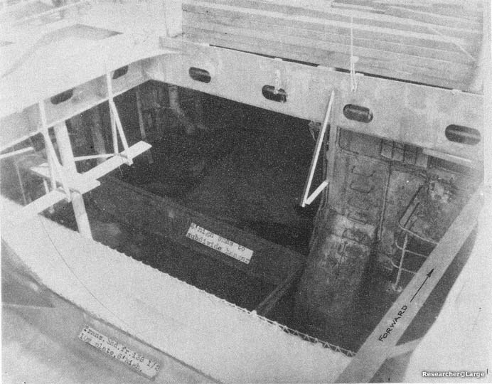
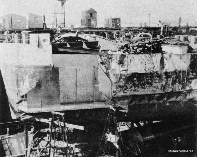
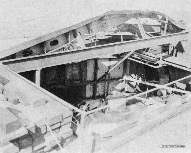
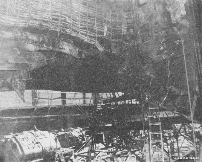
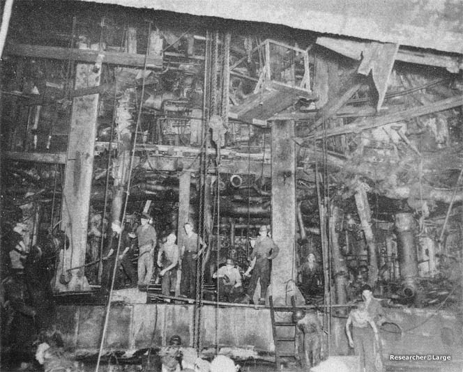
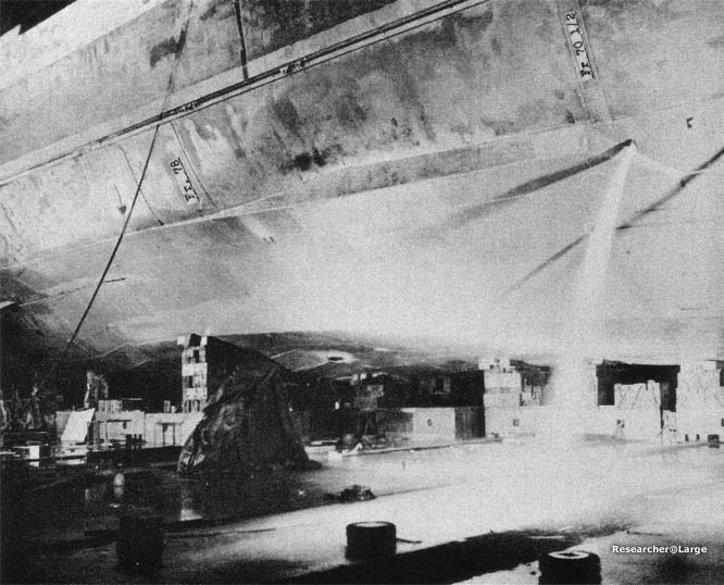
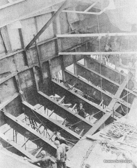
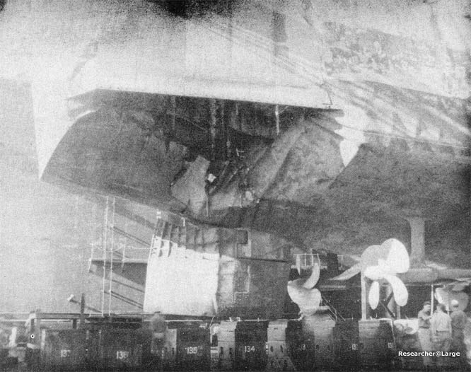
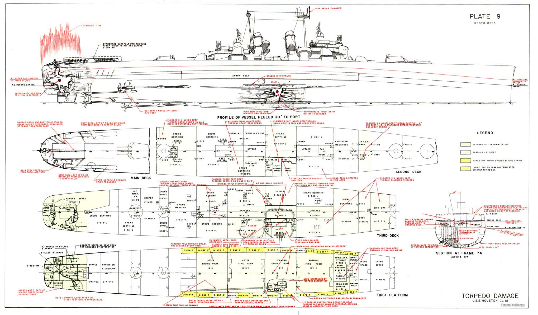
1. At 1841 on 14 October 1944, while HOUSTON was heeling to port during a high speed turn to starboard, an aircraft torpedo detonated in contact with the bottom at frame 75, midway between the centerline keel and the starboard bilge keel. The forward engine room, B-2, flooded immediately through a 10" diameter hole in the shell plating. Bottom structure was seriously damaged over an area 32' long by 24' athwartships (Photo 10, Plate 9). The keel was hogged 14" and cracked at frame 74 (Photo 11) Wrinkles extended around the girth to the bottom of the port side armor belt at frame 74. As HOUSTON was wracked by the seas, compression wrinkles developed amidships in the port main deck stringer plate and in some port main deck longitudinals. The forward fireroom, B-1-1, flooded in 10 minutes through a wrinkled and torn section of bulkhead 69, about 24 feet from the explosion. Boilers in this space were secured from valves on the third deck. The after fireroom, B-3-1, flooded very quickly through tears in the badly crumpled area at the bottom of bulkhead 79. Despite serious local damage, bulkhead 79 supported the bottom structure and limited distortion of the shell aft of that point (Photo 10). Propeller shaft #1 was broken, and drag on the propeller pulled the shaft 5 1/2' aft. This damaged the shaft glands in the stern tube and bulkhead 91, permitting the after engine room, B-4, to flood in about 30 minutes. No. 1 LP turbine was thrust upward against the overhead of B-2 and opened two scarfed joints in the 2" STS armored 3rd deck in the machine shop, B-307L. Spaces on the third deck flooded through these openings and damaged access trunks. The extensive flooding on the 2nd and 3rd decks is shown on Plate 9. HOUSTON underwent a period of negative initial stability while B-1-1 and B-4 were flooding. The vessel finally stabilized at a displacement of 20,900 tons with 6400 tons floodwater aboard, GM of +0.2", a 16° starboard list, and the main deck awash when the ship rolled.
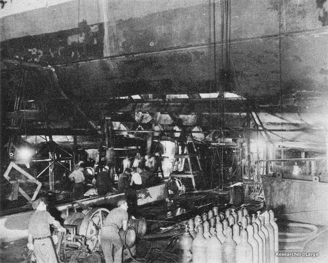
2. HOUSTON undertook, effectively, measures to establish flooding boundaries, unwater partially flooded compartments, reduce seepage, jettison topside weights and shore weakened
|