If you can see this text here you should update to a newer web browser

Normal | Highlight & Comment Highlighted Text are in Yellow


Aer-E-342-BEM
CV/S64
NAVY DEPARTMENT
BUREAU OF AERONAUTICS
WASHINGTON 25, D,C.
 

CONFIDENTIAL7 May 1945

AIRCRAFT CARRIER BULLETIN NO. 11

Subj:    Aircraft Carrier Lights for Night Flight Operations.
 
Refs: (a) Aircraft Carrier Bulletin No. 4.
(b) Aircraft Carrier Bulletin No. 6.
 
Encl: (HW)
(A) BuAer Sketch S.I. 967 "Typical Lighting Arrangement for Night Flight Operations" dated 4 April 1945.

1.  This aircraft carrier bulletin is issued to cancel references (a) and (b) and consolidate information on old and new equipment used for night flight operations on aircraft carriers.

2.  The following is an outline of the special lights and signal system installed in the aircraft carrier as aids to the pilots in conducting night flight operations:

    (a) Signal and Homing Lights:  Two gimbal mounted white lights installed on the island to provide automatically or manually keyed signals, or a steady light. Cams are provided for the pulsator so that letter calls may be assigned for carrier identification. The lights have a maximum range of 8,000 yards, a 4Oº vertical light spread, with lower cut-off parallel to the horizon, and a combined azimuth angle of not less than 360°. The purpose of these lights is to positively identify the carrier to pilots within visual range, to establish a reference point for airplanes in the vicinity of the carrier and to provide a means for homing. A secondary use of the light is to permit visual signaling to planes in the vicinity of the carrier. These lights are controlled by switches at Fly Control(s) and Flight Deck Lighting Control Station(s). A pulsator and a manual key are located at the Flight Deck Lighting Control Station and a manual key at Fly Control Station.

    (b) Identification Lights:  Three (3) of these lights are installed to provide a steady light of predetermined colors to aid pilots in locating, identifying, and establishing the course of their parent carrier when the plane is above the 40º upper light cut-off of the signal and homing lights. The lights are provided with red, green, amber, and white color roundels, have a light spread from 40º above the horizon to vertical, and are visible at an altitude of 10,000 feet. The angle of azimuth is 360°. The lights are mounted off the starboard walkway, and supersede the glow lights. These lights are controlled by switches located at Fly Control(s) and the Flight Deck Lighting Control Station(s).

NOTE: The signal and homing lights and identification lights are the only lights discussed herein which have no connection with the actual mechanics of night landing operations. Consequently, service experience may indicate the desirability, under special circumstances of installing them temporarily on an escorting vessel.

    (c) Bow Designation Lights:  Red lights, gimbal mounted, installed at the starboard and port bow of the carrier. These lights have a maximum range of 2600 yards, a 45º vertical light spread with lower cut-off parallel to the horizon, and a 160ºangle of azimuth. The mid point of the angle of azimuth is 0º relative for the starboard light and 330° relative for the port light. The purpose of these lights is to provide orientation and to indicate the

1


Aer-E-342-BEM
CV/S64

CONFIDENTIAL

Subj:    Aircraft Carrier Lights for Night Flight Operations.
- - - - - - - - - - - - - - - - - - - - - - - - - - - - - - - - - - - -

course of the carrier to pilots flying in the vicinity. These lights are controlled by switches located at Fly Control(s) and the Flight Deck Lighting Control Station(s).

    (d) Signal Light Bars:  Red and white group of gimbal mounted lights located on the outboard edge of port walkway aft. These have the same characteristics as the bow designation lights with mid point of visibility on port beam. The lights are mounted in pairs with the forward two pairs red and the after two pairs white. There are four (4) pairs of fixtures with the forward pair located opposite a turning light located on the superstructure, and the after pair located near the stern. The other two pairs are mounted between the forward and after pairs so that the four pairs are equally spaced. These lights provide a means of orientation1 to pilots flying on the downwind leg and when approaching the groove. They may also provide a means of indicating ships readiness to commence landings. These lights are controlled by switches at Fly Control(s) and Flight Deck Lighting Control Station(s).

    (e) Turning Light:  This light is installed at a height of approximately 30 feet above the flight deck and on the port side of the island structure opposite the forward signal light bar fixture. The characteristics and light distribution of this light are the same as the signal light bar fixture. The color of the light is red. The purpose of this light is to provide in conjunction with the forward pair of signal light bars a reference range to assist the pilot in determining when to start his turn from the downwind leg of his landing pattern. This light is controlled by a switch located at Fly Control(s) and the Flight Deck Lighting Control Station(s).

    (f) Landing Deck Lights:  These lights are installed at the flight deck level to outline the flight deck for landing and take-off. The two forward lights on the starboard side and the two forward lights on the port side are red, all other lights are white.

(1)  The white lights have a maximum range of 1800 yards, and a vertical light spread of 14.5° with the lower light cutoff parallel to the top of the flight deck. The angle of azimuth is l60°.
(2) The red lights have a maximum range of 400 yards and a vertical light spread of 30° with the lower light cutoff parallel to the top of the flight deck. The angle of azimuth is 104º
(3) The starboard row of white lights and the aftermost port white light have a horizontal light distribution from 130º to 290º relative. All other white landing deck lights on the port side have a horizontal light distribution from 100° to 260° relative.
(4) The starboard red lights have a horizontal light distribution from 156° to 260º relative. The port red lights have a horizontal light distribution from 100° to 204° relative.
(5) The landing deck lights are installed and mounted so that the rows of lights will be as nearly as possible in straight lines, parallel to the ship's centerline, as is

2


Aer-E-342-BEM
CV/S64

CONFIDENTIAL

Subj:    Aircraft Carrier Lights for Night Flight Operations.
- - - - - - - - - - - - - - - - - - - - - - - - - - - - - - - - - - - -

     compatible with the contour of the flight deck. Red lights may be designated for the white lights in which case all red lights except the two forward lights on each the starboard and port bow, would have the same characteristics and be installed the same as the white landing deck lights.

    (g) Depth Perception Lights:  These lights are provided to assist the pilots in determining their height above the deck when landing. These lights are under development, and will be furnished when ready.

    (h) Guide Lights:  White lights mounted athwartships semi-flush with the deck and located just forward of the after ramp, just forward of the last (third) barrier, and just aft of the forward ramp. There are five lights mounted at the after ramp and three lights mounted at the barrier and the forward ramp. These lights have a maximum range of 400 yards and a 20° vertical spread of light showing aft with lower cut-off parallel to the flight deck. The purpose of these lights is to provide a horizontal reference line for pilots during the final stage of landings and during take-offs. These lights are controlled by switches at Fly Control(s) and Flight Deck Lighting Control Station(s).

    (i) Ultra-Vlolet Flood Lights for Landing Signal Officer:  Two (2) ultraviolet fixtures installed at the landing signal officer's platform and mounted so as to flood the landing signal officer with ultra-violet light. By this means illumination is provided for fluorescent equipment used by the landing signal officer when directing pilots in their night landing approach. These lights are controlled by switches located at the landing signal platform.

    (j) Landing Signal Wands:  Two hand held lights provided for the landing signal offlcer, to be used as an alternate device for signalling when directing pilots in their night landing approach. These lights are approximately 36 inches long and equipped with six 12 volt candelabra base lamps on 6 inch centers. Red light is produced by the use of red lamps, or a red pliofilm cover over white lamps. These lights are energized by an electrical outlet and dimming rheostat provided at the landing signal station. A 12 volt battery is furnished for standby use in case of a failure of the normal source of supply.

Dimmers for controlling the intensity of all of the above lights except the ultra-violet flood lights and wand lights are located at the Flight Deck Lighting Control Station(s).

3.  The lights discussed above are those visible to the pilots for orientation and landing purposes. There are, in addition, certain lights and signal systems installed in the ship for controlling flight operations. These lights are discussed below:

    (a) Flight Control Ready Light System (Circuit RF):  Red and green lights mounted on the island with repeaters at the hangar control station, landing signal station, steering station, catapult station and other locations. The purpose of this system is to indicate to personnel concerned readiness of the vessel for flight operations. Control is by switch at Fly Control(s).

    (b) Barrier Ready Light System (Circuit BL):  A signal system between the flight deck officer and the landing signal station to indicate when barriers are up and landing area is clear for a landing. A red light for indicating

3


Aer-E-342-BEM
CV/S64

CONFIDENTIAL

Subj:    Aircraft Carrier Lights for Night Flight Operations.
- - - - - - - - - - - - - - - - - - - - - - - - - - - - - - - - - - - -

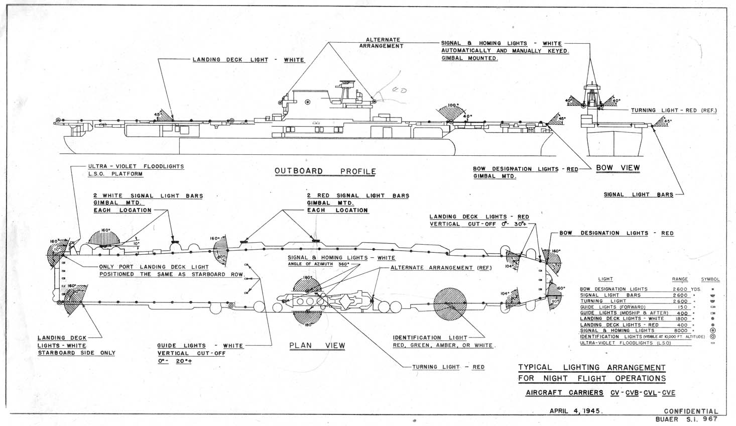
when the barriers are down or the deck is not ready, is located at landing signal station. Its control is by a switch located in the barrier area which la operated by the flight deck officer. Barrier indicator lights are being developed to indicate primarily to the barrier operators which barriers are up. This system will permit more intelligent use of barriers and will tend to speed up night operations.

    (c) Landing Observer's Signal System (Circuit PL):  This system provides the landing observer with a means of indicating to the landing signal officer that an approaching airplane is making an improper approach. It consists of a portable contact maker at the landing observer's station in the starboard after gallery walkway and a type B6 bell and a red dial lamp type indicator at the landing signal stations.

    (d) Deck Signal Wands:  A wand light consisting of a 5 inch length of luscite tube inserted in a standard flashlight. These wands are used in pairs by taxi directors using basically the same signals as used in daylight operations.

4.  The approach light is the only special light Installed in aircraft for night carrier operations. It is located in the leading edge of the port wing outboard of the propeller arc. The light is actuated by an automatic switch when the arresting hook is in the down position. The approach light circuit has an additional switch (AN3015) paralleling the automatic switch. This switch permits lighting the approach light while practicing night carrier landings ashore. Care should be taken to install the guard provided to secure this switch in the open position prior to carrier operations.

5.  It should be noted that manufacture, installation and maintenance of the lights and signal systems discussed above, which are attached to the ship or connected to the ship's power supply, are under the cognizance of BuShips. Characteristics of the lights, however, are subject to the approval of BuAer.

6.  To Insure the proper functioning of the lights and signal systems, strict inspection must be maintained. All circuits should be energized prior to each night's flight operations to assure that all circuits are in operating condition. Once each week all fixtures should be cleaned and checked for burned out lamps. Care should be exercised that proper size lamps are used for replacements.

7.  Add to Index of Aircraft Carrier Bulletins the following and delete Aircraft Carrier Bulletins 4 and 6:

Bulletin
   No   
Subject Classification
11

Aircraft Carrier Lights for
Night Plight Operations.

Confidential

- 4 -


SOURCE:
National Archives & Records Administration, Pacific Northwest Region, Seattle
Record Group 181, Ship Files Circa 1940-1950

Transcribed by RESEARCHER @ LARGE. Formatting & Comments Copyright R@L.

Ships Home | Researcher@Large Home