If you can see this text here you should update to a newer web browser
Normal | Highlight & Comment Highlighted Text will be in Yellow
|
CONFIDENTIAL TECHNICAL REPORT
_____________ WAR DAMAGE REPORT--U.S.S. TICONDEROGA (CV-14)
ACTION OF 21 January 1945. DATE
PUGET SOUND NAVY YARD INDUSTRIAL DEPARTMENT SCIENTIFIC & TEST GROUP CODE 274
|
|
CONFIDENTIAL WAR DAMAGE REPORT -- U.S.S. TICONDEROGA (CV14) Prepared by Puget Sound Navy Yard
TABLE OF CONTENTS
|
|
WAR DAMAGE REPORT -- U.S.S. TICONDEROGA (CV14)
- 1 -
|
|
WAR DAMAGE REPORT -- U.S.S. TICONDEROGA (CV14)
Section III - Hull Fittings 1. Damage to hull fittings from the hit on the island structure was minor. The signal yardarm was enveloped in flames which destroyed equipment mounted on it. The signal halyards, which were consumed by flames, spread the fire to flag bags. The 20mm R.S. locker for gun No. 32 (top of pilot house at frame 101 port) was punctured by fragments, but the ammunition did not detonate. One cartridge holder for 40mm ammunition in the bulwark R.S. stowage for quad. mount at frame 85 on the forward Air Defense Level was exploded. The canvas cover for this ammunition burned, but no other explosion occured. Fragment damage to three 12-inch signal searchlights put them out of action. 2. The hit on the Flight Deck caused more extensive damage to hull fittings than the hit on the lsland Structure. At the time of the hit, No. 1 airplane elevator was loaded with one plane and starting up from the Hangar Deck; the bomb explosion on the Hangar Deck set fire to the plane which temporarily put the elevator out of action. The elevator platform showed evidence of intense heat as the wood decking was charred to a depth varying from one-quarter to one-half inch, but no appreciable distortion of the platform was apparent. 3. Fragments from the bomb which exploded at the Hangar Deck, or from the secondary explosion of the burning plane on the elevator platform, struck the starboard catapult leads at a height of about three to five feet above the Hangar Deck piercing the cable tubes and partially severing the two inboard starboard cables. The starboard catapult was not used after the hit due to damage to the cables and flooding of the pump room (A405AE) by water from the Hangar Deck which came through the hatch in the elevator well at about frame 32. However, the port catapult remained operative. 4. The forward starboard boat and airplane crane was struck by the bomb nose fuse which pierced the chord of the jib at a point about ten feet from the center of rotation of the crane. The operation of the crane was not impared (as regards machinery) although it was not used for heavy loads until repaired. 5. Two bomb elevators adjacent to the explosion area at the Hangar Deck were damaged by fragments and fire. The elevator trunk at frame 58 starboard (A-417T) was pierced by fragments above the Hangar Deck and the inboard side was caved in. The elevator platform lodged near the Forecastle Deck level and was later shored in this position since the electrical leads and controls were destroyed by fire and the guide rails were out of line due to distortion of the trunk. The elevator trunk at frame 79 starboard (B-403T) received two large holes in the forward side above the Hangar Deck and a large dent in the after side, and the flame seal door was damaged by smaller fragments. No spread of the fire via the trunks occurred.
- 3 -
|
|
WAR DAMAGE REPORT -- U.S.S. TICONDEROGA (CV14)
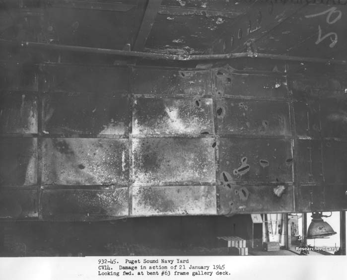
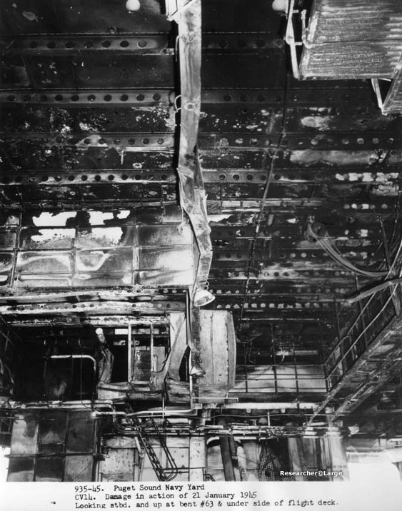
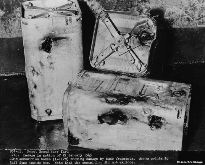
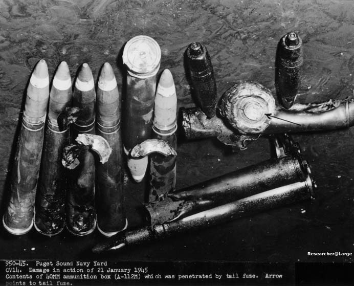
Section III Hull Fittings (continued) 6. The 40 mm R.S. room at frame 54 to 58 on the Hangar Deck port was struck by large fragments, including the tail fuse of the bomb which exploded at the Hangar Deck. The inboard bulkhead was pierced, and several cans of ammunition were damaged. Although fragments were lodged in the cans and the shells themselves damaged, no detonation of ammunition resulted. (The effect of the fragments on the ammunition is clearly shown in Photos. Nos. 951-45 and 950-45.) 7. The droppable gasoline tank stowage for a aircraft at the Gallery Deck level from frames 44 to 58 was destroyed by a combination of the fire at the Hangar Deck, the impact of the plane, and fragments from the bomb explosion. The close spacing of this stowage seriously hampered the effectiveness of sprinkling system since the tanks were below the sprinklers. This caused water to come down in streams rather than in a spray. 8. Other items damaged by the fire on the Hangar Deck include arresting gear units 1A, 2A and 3A which were exposed to great heat. The chain hoist under the Flight Deck at frame 65 starboard was damaged so badly by fire that replacement was required. See Photo. No. 935-45. All other damage to hull fitting items in this area (Hangar Deck and above, frames 45 to 85) was minor. 9. Hull fitting items of major importance to the fighting efficiency of the ship, for the most part, escaped permanent crippling damage. Some units, such as the starboard catapult and No. 1 bomb elevator, were rendered inoperative, but alternate units were available. The efficiency of the ship was reduced in some degree but the damage was, in general, the natural effect of fire and explosion and no loss of function of important equipment was due to poor design features. 10. The closely spaced droppable gasoline tank stowage is necessary due to the large number stowed and the space available for stowing. This type of overhead stowage includes a light weight platform which blanks off the Hangar Space below from sprinkling. To correct this unsatisfactory condition, the Yard installled additional sprinkler systems under the stowage platform similar to those recently installed on CV13 and CV17. It is recommended that all similar type tank stowage now in use be investigagted and if conditions warrant, action be taken to insure adequate sprinkling below the stowage platforms.
- 4 -
|
|
WAR DAMAGE REPORT -- U.S.S. TICONDEROGA (CV14)
Section IV - Arrangements
1. This vessel and others of the class have experienced difficulty in fighting fires in the Second Deck area due to the presence of smoke and gases. The recent battle experience of the BUNKER HILL shows the need for better fume tight subdivision on the Second Deck between frames 79 and 131 so that smoke and gases may be contained to the compartments in which the fire exists. 2. In reference (g) the Yard recommended replacement of arches and metal joiner doors with quick acting or structural doors between bulkheads 79 and 131 on the Second Deck. It is noted from reference (h) that the later CV9 class vessels are so compartmentalized.
- 5 -
|
|
WAR DAMAGE REPORT -- U.S.S. TICONDEROGA (CV14)
Section V - Piping 1. The piping damage sustained by the TICONDEROGA (CV14) was similar to the described in reference (a) (This may be an error, the Franklin report was reference (f)) for the U.S.S. FRANKLIN (CV13). The description of the performance of the various piping systems given in the FRANKLIN report applies to the TICONDEROGA as well. 2. After study of the damage on the TICONDEROGA the following additional points are discussed:
- 6 -
|
|
WAR DAMAGE REPORT -- U.S.S. TICONDEROGA (CV14)
Section VI - Ordnance 1. The plane that crashed into the forward Gun Director resulted in the following damage to ordinance equipment:
- 7 -
|
|
WAR DAMAGE REPORT -- U.S.S. TICONDEROGA (CV14)
Section VII - Radar and Radio 1. Damage to radar equipment was extensive. The only units operating when the ship arrived at the Yard for repairs were the SG and the after Mk. 12 and Mk. 22 radars. The major units damaged are listed below:
2. Radio equipment was also extensively damaged as a result of the explosions and fire. A brief description of the units affected is given below:
- 8 -
|
|
WAR DAMAGE REPORT -- U.S.S. TICONDEROGA (CV14)
Section VII - Radar and Radio (continued)
- 9 -
|
|
WAR DAMAGE REPORT -- U.S.S. TICONDEROGA (CV14)
Section VIII Electrical and Machinery
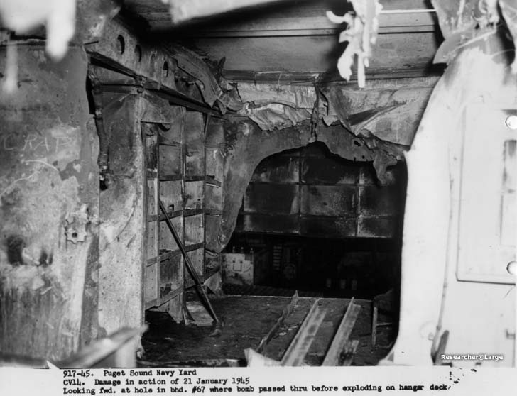
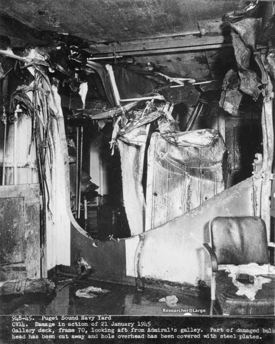
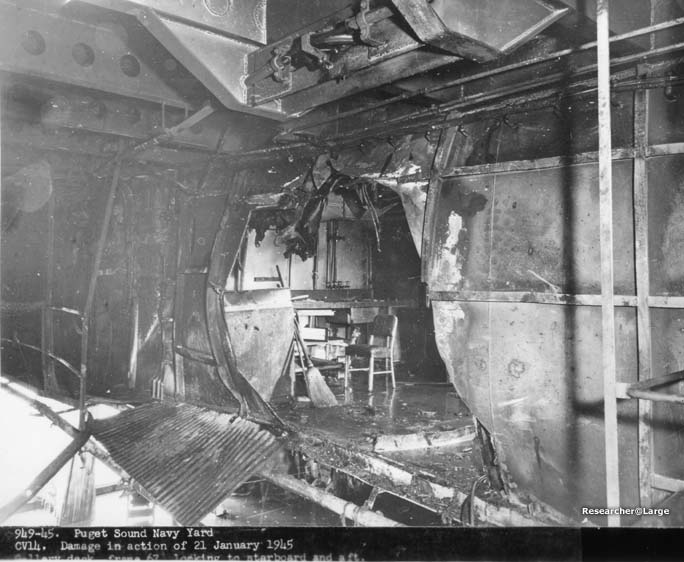
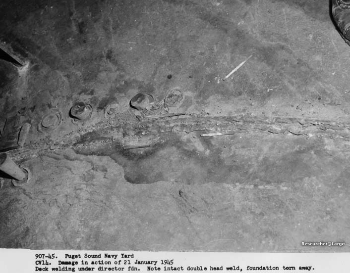
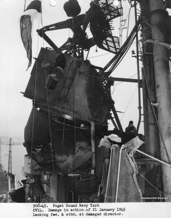
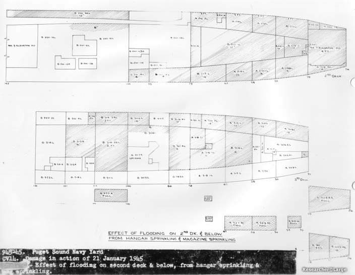
1. The major portion of the damage to electrical equipment below the Flight Deck was due to fire, explosions of gasoline from airplanes in the hangar space, and water from the hangar sprinkling system rather than to fragments from the bomb explosion in the Hangar Space. Local electrical damage in the forward Air Defense Station and Island Structure was caused by the crash hit on the Mk. 37 Director No. 1. The area in which electrical equipment was damaged by water is shown on photo No. 945-45, and damage by fire is shown on the sketch, Appendix C. 2. Damage was severe at the forward Air Defense Station. Electrical equipment at this station was practically demolished by explosion and subsequent fire. Electrical damage was also severe in the Captain's and Admiral's Country (frames 68-80, Gallery Deck), where all equipment was either destroyed or completely disabled by fire, as shown by Photos. Nos. 915-45, 917-45, 948-45 and 949-45. 3. Destruction of electrical equipment at the forward Air Defense Station resulted in a complete loss of all the vital functions of the station. Damage to the Mk. 37 Director and associated cables at this level caused loss of primary control of the forward 5"/38 twin mounts and auxiliary control of all 5"/38 single and 40 mm quad. mounts forward of the island. Fire damage in the Hangar Space and on the Second Deck caused temporary loss of control for 40 mm quad. mounts Nos. 1, 2 and 4, and put all electrical circuits at 40 mm quad. mounts Nos. 6 and 6A out of commission. Lead sight circuits to 20 mm guns in Battery I and Battery II were lost due to damage in the Hangar Space. The 40 mm ammunition hoist serving ready service room B-0703-M, for 40 mm quad. No. 7 was put out of commission by fire damage to power and control circuits. 4. The functions of launching, handling, and arming of aircraft were impared to a considerable extent by electrical damage throughout the forward section of the vessel. The starboard catapult was rendered inoperative by the flooding of all electrical machinery in compartment A-405-AE. Upper stage bomb elevators B-1-B and B-2-B were inoperative due to fire and flooding of their control circuits. Electric control of airplane elevators 1,2 and 3 were lost immediately after the first hit. However, manual control was still available on all airplane elevators, permitting No. 1 elevator to be raised to the Flight Deck where it was secured. Ship's force later restored electrical control of No. 3 elevator by drying out a control connection box which had been flooded. The night flight lighting system forward of the island was disabled as a result of damage to supply cables in the Hangar Space. The homing lights on the Island Structure were disabled by damage to control leads between Primary Fly and the forward Flight Control Station. 5. Except for damage to some pelorus stands on the Flag Bridge and a gyro repeater at Air Defense Forward, ship's control circuits were not damaged. 6. Lighting was lost in several large areas due to damage to transformer banks on the Second and Third Decks from hangar sprinkling water which drained into these areas from open hatches on the Hangar Deck. Ship's force later
- 10 -
|
|
WAR DAMAGE REPORT -- U.S.S. TICONDEROGA (CV14)
Section VIII - Electrical and Machinery (continued)
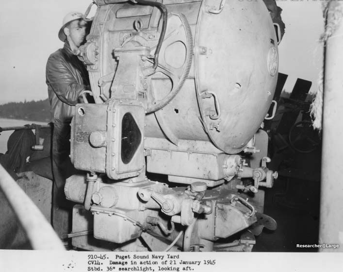
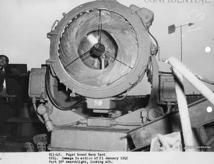
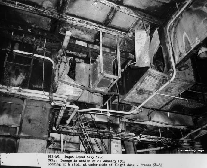
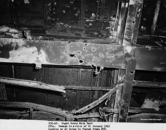
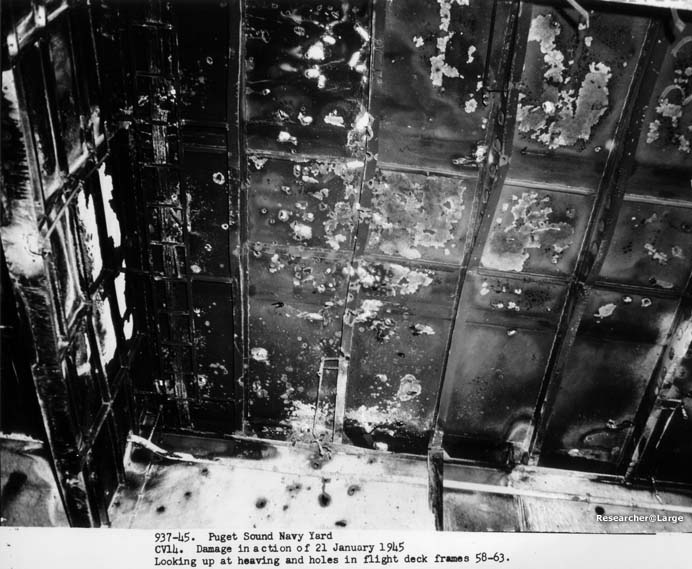
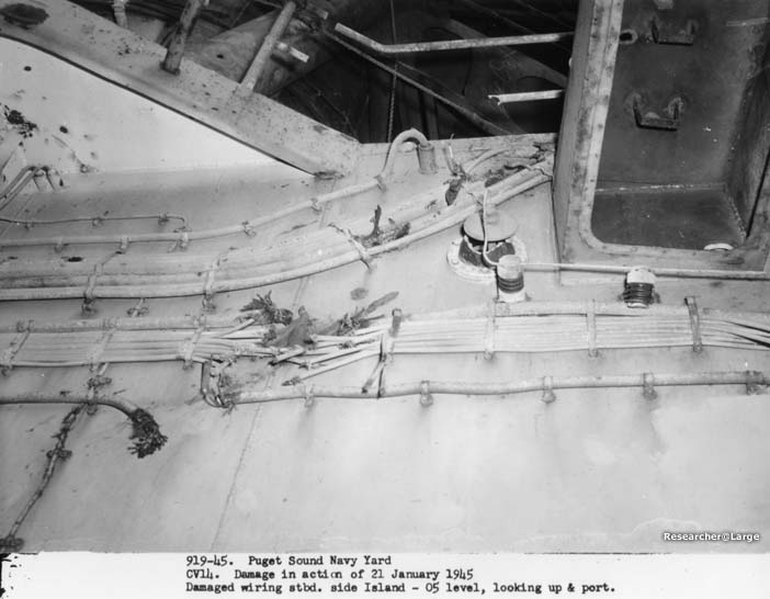
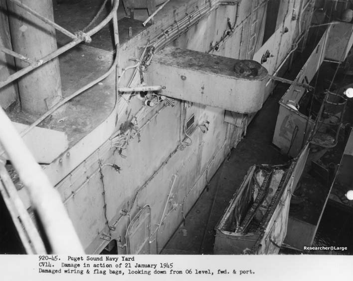
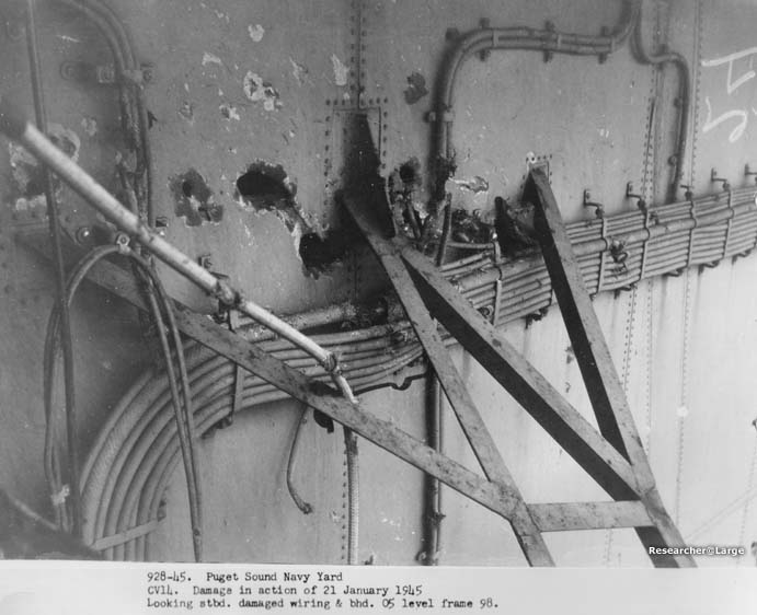
6. 7. Fire and fragment damage caused loss of all voice communication throughout the forward half of the Island Structure, all of the Flight Deck and Hangar Space, and the Gallery Deck forward, with the exception of some sound powered telephone circuits. The sound powered communication unaffected by damage was sufficient to pass all orders necessary for the completion of damage control measures. All damaged circuits were isolated by the ship's force so that other outlying networks of these systems were not affected. Inter-ship communication by means of visual signaling was impaired to a considerable extent by the destruction of the 24 inch searchlights and by severe damage to three 12 inch searchlights. Both 36 inch searchlights were also disabled by fragments, as is shown in Photos Nos. 910-45 and 911-45. 8. Casualty power generators No. 1 and 2 on the Hangar Deck became inoperable due to fire damage and salt water spray from the hangar sprinkler system. Numerous casualty power risers and bulkhead terminals throughout the damaged areas were grounded by salt water from fire hoses or sprinklers. 9. Fire and water damage to the electrical equipment for ventilation systems caused the temporary loss of the major portion of ventilation forward of frame 125 on all decks above the Fourth Deck, including the Island Structure. The ship's force later restored electrical service to a sufficeient number of vent sets to provide necessary ventilation. It was found that the most frequent cause of lose of ventilation was due to fire hose water spray which entered the drip proof case of the motor controllers. 10. Exclusive of demolished equipment within the blast area, investigation revealed that electrical equipment withstood shock satisfactorily. 11. Considerable fire damage occured to cables in wireways on the overhead of the Hangar Space and necessitated the replacement of all cables in the wireways forward of frame 100. Typical examples of the exposed wireways in the Hangar Space are shown in Photos Nos. 931-45, 936-45 and 937-45. A number of important cables on the Island Structure in weather location are exposed to strafing attacks and bomb fragments. Several cables were cut by fragments, as shown in Photos Nos. 919-45, 920-45 and 928-45. 12. The investigation has revealed several faults which it is believed can be corrected by better design. Comments and recommendations are as follows:
- 11 -
|
|
WAR DAMAGE REPORT -- U.S.S. TICONDEROGA (CV14)
Section VIII - Electrical and Machinery (continued)
- 12 -
|
|
WAR DAMAGE REPORT -- U.S.S. TICONDEROGA (CV14)
Section VIII - Electrical and Machinery (continued)
13. Machinery damage was minor, and consisted of fragment damage to the smoke pipe, whistle, and siren and slight damage to the propellers by debris thrown overboard during the action.
- 13 -
|
|
WAR DAMAGE REPORT -- U.S.S. TICONDEROGA (CV14)
Section IX - Ventilation 1. A brief description of the ventilation equipment damaged by the two hits and pertinent comments are given in the following paragraphs:
2. Some unusual conditions which occured due to unsatisfactory ventilation design and failure to obtain the desired ventilation conditions for battle security are given below:
start - 14 -
|
|
WAR DAMAGE REPORT -- U.S.S. TICONDEROGA (CV14)
Section IX - Ventilation (continued)
- 15 -
|
||||||
|
WAR DAMAGE REPORT -- U.S.S. TICONDEROGA (CV14)
Section X - Flooding and Stability
1. The ship's personnel report that the ship was turned to starboard immediately following the first hit. This action caused a list to port and the ship continued this manuever until the flooding of port side voides B-28V, B-44V, and B-74V produced a permanent list to port. 2. Examination of Photo No. 945-45 indicates that considerably more water was taken aboard by sprinkling than was reported in paragraph 5 of reference (a). However, it should be noted that the depths shown on the diagram are merely estimates of the water in the various compartments at some time during the flooding. No attempt has been made to determine the effect of free surface on stability since the extent of flooding at any instant is not definately known. 3. The recommendations of reference (f) as to disposal of fire fighting water to prevent unnecessary flooding, are applicable to this vessel as well.
- 16 -
|
|
- 18 -
|
||||||||||||||||||||||||||||||||||||||||||||||||||||||
| If you would like to view a link list of all the photos included in this report and their captions you should check out Appendix "A". |
SOURCE: National Archives & Records Administration, Seattle Branch
Record Group 181, Ship Files ca 1940-1950
Declassification Review Project NND 958357
Transcribed by RESEARCHER @ LARGE. Formatting & Comments Copyright R@L.
CV-14 Ticonderoga Kamikaze Attack Home |
Ships Home | Researcher@Large Home