If you can see this text here you should update to a newer web browser

Normal | Highlight & Comment Highlighted Text will be in Yellow, but there are none yet

RESTRICTED


Ship: USS WADLEIGH (DD689)
Cause of Damage: Mine
Date: 16 September 1944
Place: Kossol Passage, Palau Islands
Class: DD 445
Standard Displacement: 2050 tons
Length Overall: 376' 5"
Extreme Beam: 39' 7"
Draft Before Damage: 13' 6"
Launched: 7 August 1943


1.     At 1428, 16 September 1944, while WADLEIGH was engaged in mine demolition operations, an unswept mine detonated at frame 112, midway between the centerline and starboard bilge keels. The ship was heaved upward in a critical hogging condition that caused a compression wrinkle around the bottom from deck edge to deck edge at frame 111. B-2 and B-3-1 flooded immediately through the hole in the shell, and B-4 flooded in about 2 minutes through a damaged area around the shaft gland in bulkhead 130 1/2. The flooding reduced reserve buoyancy by 1200 tons and produced a sagging condition that caused the damaged structure to fail in tension with a loud report. A11 power was lost. The hole in the bottom extended between frames 106 and 118 and between the centerline and longitudinal 7, starboard (Plates l9 and 21, Photo 36). The fracture in the shell plating extended between the lower edges of the port and starboard F strakes. At the fracture the thickness of a 1/2" plate was reduced to 5/16" and failure occurred in shear at 45°. F and G strakes, port and starboard, were kinked inward a maximum of 5" at the lower edge of F strake. The section modulus was reduced to about 14% of the intact value, and WADLEIGH undoubtedly would have broken in two had she not been in a protected lagoon.

2.     WADLEIGH was towed to the nearby anchorage. The principal emergency damage control measures undertaken to restore buoyancy, improve stability, and reduce the sagging condition were:

       (a)  CLAMP (ARS 7) made emergency repairs to bulkhead 130 1/2 which permitted pumping B4.
 
       (b)  95 tons of topside weight was removed, increasing GM 0.46'.
 
       (c)  53 tons of fuel oil was transferred.


RESTRICTED - 47 -


RESTRICTED


3.     Repair work by PROMETHEUS (AR 3) began on 23 September. Since no drydock was then available and the loss of longitudinal strength made it unsafe to tow the ship, divers fitted patches on shell plating cracks (Photo 37) in preparation for pumping flooded compartments, using a temporary caisson over the main hole in the shell. Divers made templates of the shape of the hull where good support could be obtained beyond the extremities of the hole. The caisson, made of 6" planking with 24" x 10" x 100# x 24' long I girders and weighing 20 tons, was built to these templates (Photos 38, 39, 40, 41). When completed, it was payed with marine glue, a layer of canvas was ironed on, and a second layer of marine glue was payed on. The caisson then was ballasted to overcome its 4 tons positive buoyancy and eight 3/4" ropes and chain falls to the deck were used to rig it in place. Eighteen days were required for its construction, two days for rigging and one day for caulking. When these operations had been finished, 5 feet of water were pumped. Later, the differential was reduced to 2 feet to prevent exposing the machinery to air. The caisson remained in place until WADLEIGH was drydocked in ARD 16 on 9 November 1944.

4.     Repairs in drydock began with removal of damaged structure in the largest sections that could be handled. Plating and longitudinals were cut away to places where there was relatively little deformation so that effective replacement structure could be fitted easily. Plating butts were staggered insofar as possible and the longitudinals were cut back at least one frame beyond the plating (Photo 42). Oxy-Acetylene cutting torches were used to cut steel members; the electric arc method using coated medium steel electrodes was used to cut non-ferrous metals. About half of boiler 3 and all auxiliary machinery in way of the damage was removed. Salvageable components were secured in the fireroom at the completion of repairs. While damaged structure was being cut away, great care was exercised to insure that weights in the ship were properly supported by shoring. Shoring also was placed under the stern overhang to prevent excessive pressure on the skeg as the area of the midship section was reduced.

5.     Only mild steel was available for replacing the high-tensile steel structure on WADLEIGH. Therefore, the area of the restored cross section was increased by using larger sizes for both plating and supporting structure. Between the bilge keels the area replaced was 365 square inches, a 26% increase over the original area of 288 square inches (Plates 20, 21, Table)


- 48 -
RESTRICTED


RESTRICTED

TABLE I
 
Original Plating        New Plating
 
Starboard:   Size        Area

Plate Keel - 18 x 5/8 -- 11.2
"A" Strake   48 x 1/2 -- 24.0
"B" Strake   48 x 1/2 -- 24.0
"C" Strake   60 x 3/8 -- 22.5
"D" Strake   24 x 5/16 -  7.5


Port

Plate Keel   18 x 5/8 -- 11.2
"A" Strake   48 x 1/2 -- 24.0
"B" Strake   48 x 1/2 -- 24.0
"C" Strake   60 x 3/8 -- 22.5
"D" Strake   24 x 5/16 -  7.5 178.2


Longitudinals:

Long'l #1 --- 2 x 4.36    8.72
Long'1 #2 --- 2 x13.01   26.02
Long'l #3 --- 2 x 1.72    3.44
Long'l #4 --- 2 x 4.98    9.96
Long'l #5 --- 2 x11.77   23.54
Long'1 #5 ½ - 2 x 1.72    3.44
Long'l #6 --- 2 x 4.98    9.96
93.80

Keel --------------------17.27

Strongbacks -------------/////

-----

289.27

  Size        Area

18 x 3/4 -- 13.5
49 x 5/8 -- 30.0
48 x 1/2 -- 24.0
60 x 3/8 -- 22.5
24 x 3/8 --  9.0


18 x 3/4 -- 13.5
60 x 5/8 -- 37*5
42 x 1/2 -- 21.0
60 x 3/8 -- 22.5
24 x 3/8 --  9.0
201.5


2 x  5.63 -11.26
2 x 15.75 -31.50
2 x  3.25 - 6.50
2 x  5.63 -11.26
2 x 12.50 -25.00
2 x  3.25 - 6.50
2 x  5.63 -11.26
114.54

-----------22.50

-----------27.00

-----

365.54


Percentage increase:    365.54 x 100 ------26.2%
289.27-----


RESTRICTED - 49 -


RESTRICTED


6.    All fitting, erection and welding of the replacement structure were carefully planned and rigidly supervised to attain the best possible continuity between the new and original structure; the instructions in General Specifications, Appendix 5, Specifications for Welding, being followed throughout. The largest possible sections, consistent with available handling facilities, were prefabricated both to facilitate work and to reduce the distortion due to weld shrinkage. Instructions specifically outlined were:

       (a)  Plate edges could be prepared by flame cutting, using cutting machines whenever possible, provided all scale was carefully removed before welding.
 
       (b)  Edges of 15# or lighter plating would be prepared by chipping.
 
       (c)  Butts on longitudinal strength members were to be staggered insofar as possible.
 
       (d)  Butts in a particular longitudinal or plating strake were to be butt-welded with single or double vee joints as consistent with approved practice.
 
       (e)  Seams were to be lap-welded with double fillets of the same dimension as the thinner plate.
 
       (f)  Longitudinals were to be attached to plating by continuous double fillet welds having an efficiency of 75%.
 
       (g)  All tack welds were to be inspected for cracks before production welding started.
 
       (h)  Each weld pass was to be chipped and brushed free of slag before the next pass was made.
 
       (i)  Wherever cracks were found, the entire weld was to be chipped out and rewelded.
 
       (j)  All continuous welding was to follow the step back or block sequence.
 
       (k)  Large vee-welds, particularly the transverse welds, were to be bead welds, except where downhand welding could obtain the same results.
 
       (l)  Not over 1/8 inch reinforcement was to be used on vee-welds.


- 50 -
RESTRICTED


RESTRICTED


7.    The first member installed was the keel plate. After three sections had been welded, the vertical keel which had been prefabricated in the dock basin was placed on the keel plate and welded with 1/2" continuous welds. Two 25" x l8" x 10# web brackets were installed, port and starboard, between adjacent web frames (Plate 21, Photo 43). Next, the continuous longitudinais and intercostal transverses were installed and welded (Plate 22, Photos 44 and 45). The ends of all existing longitudinals were cut back beyond the plating, the flanges were cut farther back and a 4-1 taper was used in connecting the webs and flanges of the new and replacement longitludinals (Plate 22, Photo 46). External longitudinals with web brackets at transverse frames and with tapered ends were installed in way of the wrinkle in F and G strakes, port and starboard.

8.    Next, the plating was installed. The limited equipment available to handle and fit the plating made it necessary to use comparatively short lengths. No equipment for rolling or bending plate heavier than 15# was available, therefore, heavier plate was installed in flat sections. "A°" strake was butt welded to the keel, all other seams were lapped, similar to the original plating (Plate 23, Photo 47). On the port side where wrapper plates were lapped over the crack, 12' long 6" x 30# flat bar longitudinals with tapered ends were fitted outside the shell (Photo 48). Since the original longitudinals in this area were riveted, it was necessary to fit the external longitudinals between the original ones to reduce the possibility of loosening the rivets. Sea chests in B-2-1 and B-2 were blanked to prevent leakage.

9.    A partial bulkhead was built to replace the damaged portion of bulkhead 110 (Plate 21, Photos 44 and 45). A sloping transition piece was used to fair the new bulkhead into the original one below the main deck. The ends of the bulkhead stiffeners were bracketed. A gasket type stuffing box was installed where the starboard shaft penetrated bulkhead 110 (Photo 49). Damaged pipe stanchions between the shell and main deck were replaced by columns built up from two 8" channel sections with 10# webs added,(Photo 45).


RESTRICTED - 51 -


Photo 36: WADLEIGH (DD 689)
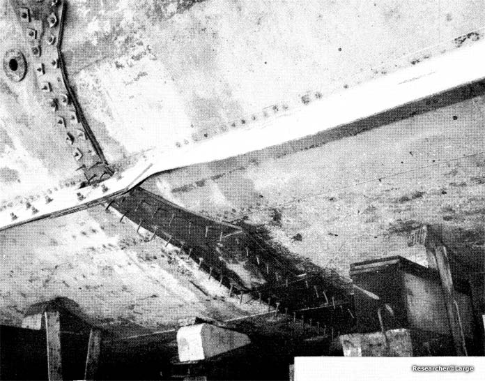
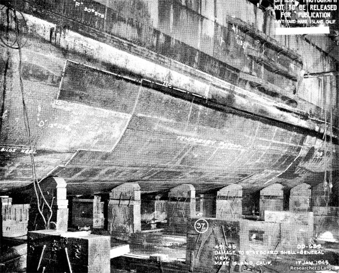
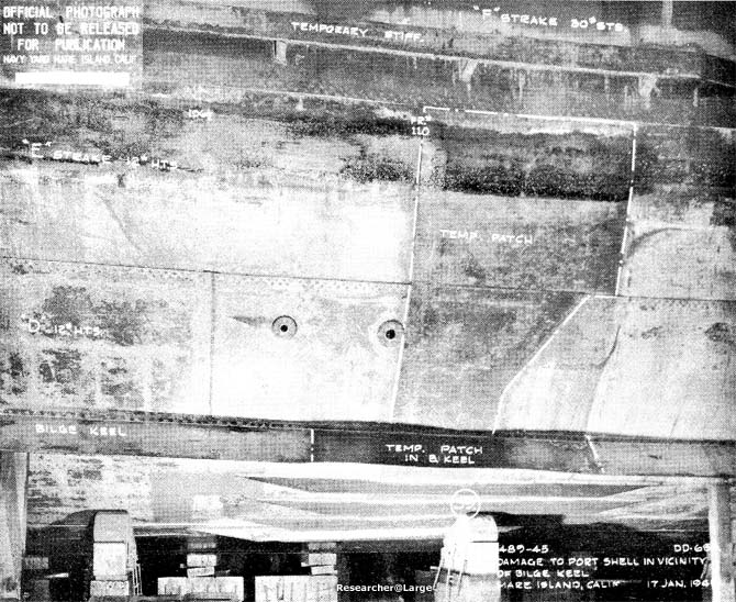
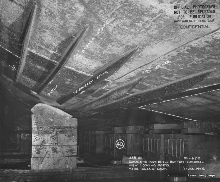
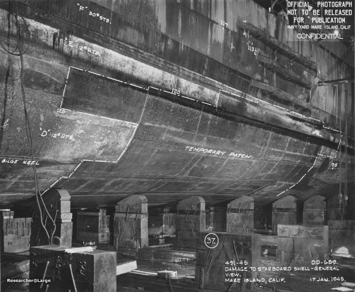
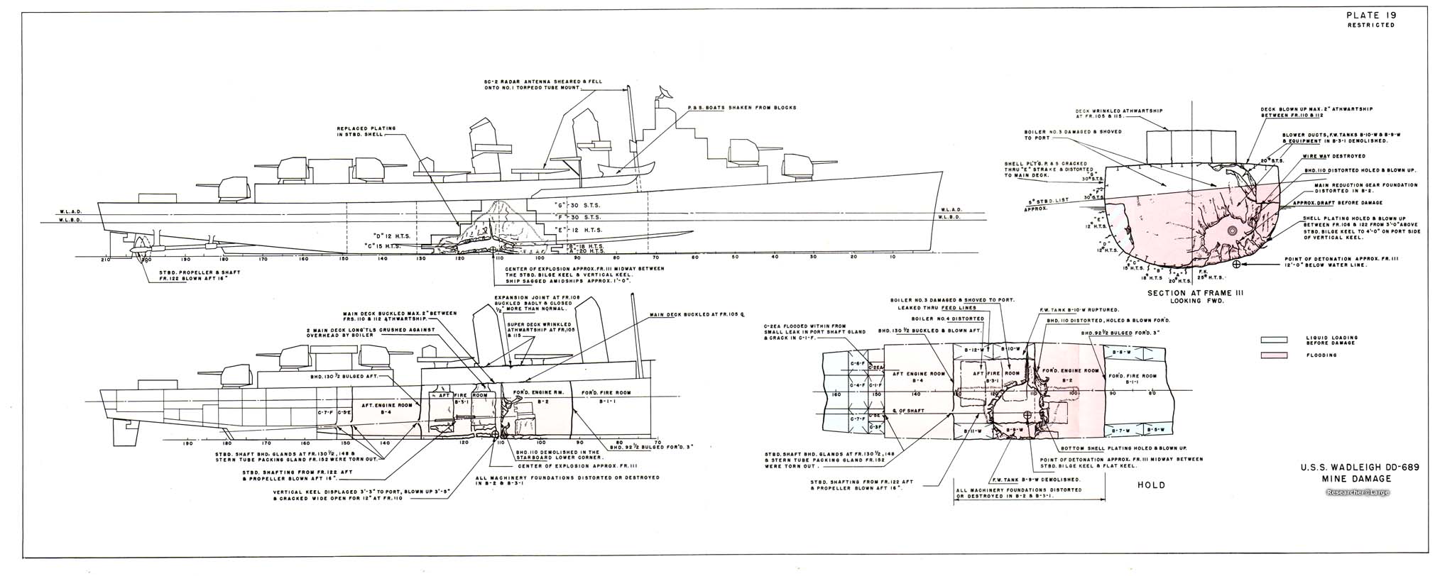
Looking forward at hole in shell, starboard side. Note divers patch above bilge keel. Plating is bent sharply inboard at end of reduction gear foundation.
 
Photo 37: WADLEIGH (DD 689)
Divers patch over crack in shell plating, frame 111, port.
 
Photo 38: WADLEIGH (DD 689)
Plan view of caisson.
 
Photo 39: WADLEIGH (DD 689)
Elevation and sections of caisson.
 
Photo 40: WADLEIGH (DD 689)
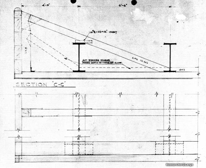
Section of caisson showing general construction.
 
Photo 41: WADLEIGH (DD 689)
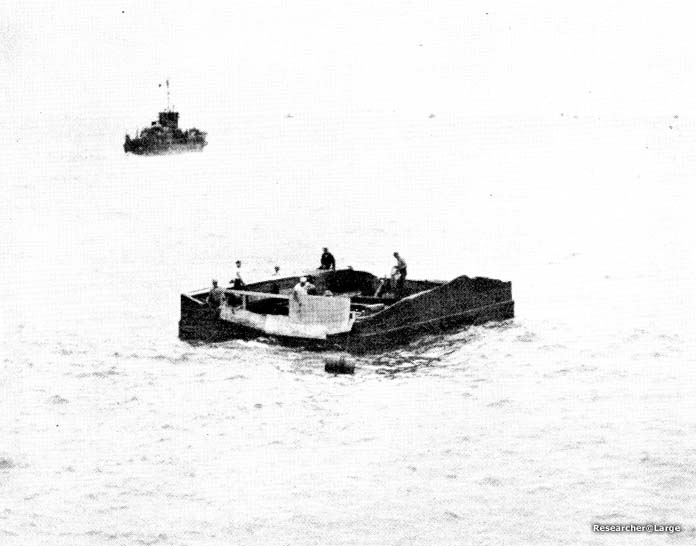
Completed caisson. Caulking material being applied to bearing edges. (Temporary sheet metal work on near end is to keep out waves).
 
Photo 42: WADLEIGH (DD 689)
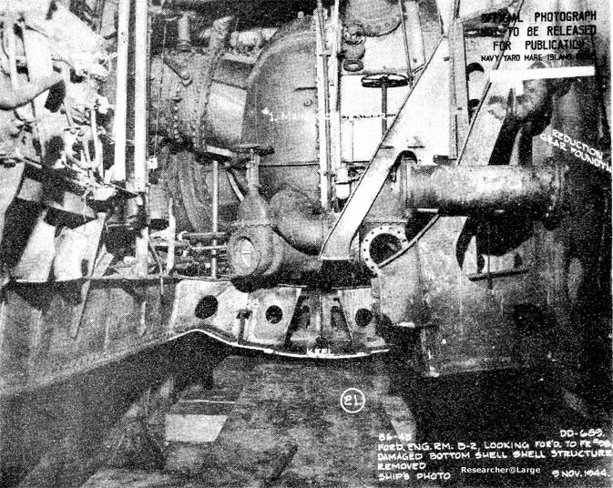
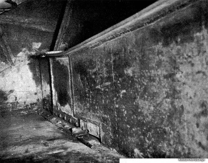
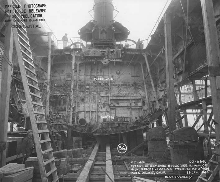
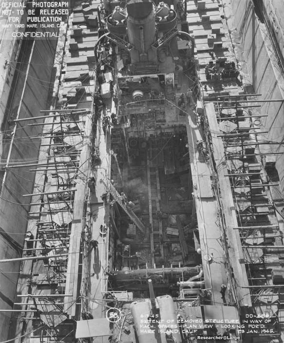
Looking forward after removal of damaged bottom plating. Note centerline keel cut beyond plating.
 
Photo 43: WADLEIGH (DD 689)
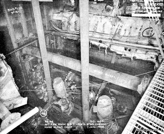
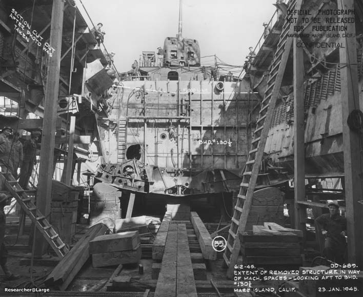
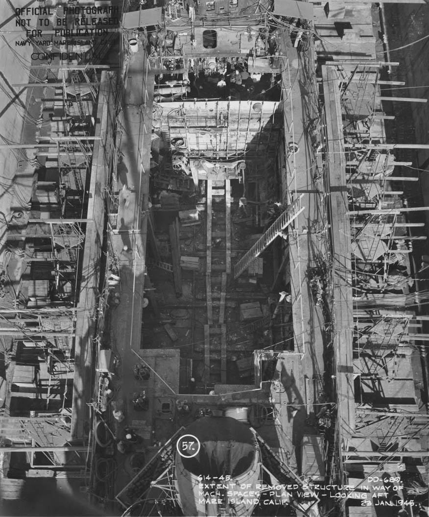
Looking aft at replacement bottom structure and bulkhead 110.
 
Photo 44: WADLEIGH (DD 689)
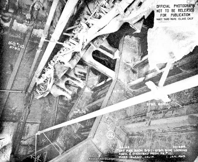
Looking forward at replacement continuous longitudinals, intercosTal transverse web frames and repaired bulkhead 110.
 
Photo 45: WADLEIGH (DD 689)
Looking forward and down at replacement bottom structure and bulkhead 110. Note replacement stanchions.
 
Photo 46: WADLEIGH (DD 689)
Detail of connection of original and replacement longitudinal #2 port.
 
Photo 47: WADLEIGH (DD 689)
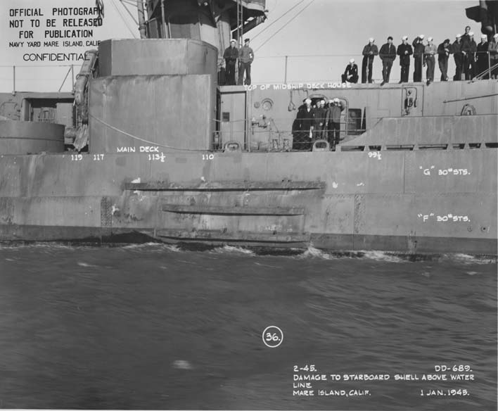
Replacement on starboard side. Note external stiffeners with web brackets and tapered ends in way of wrinkles in F and G strakes.
 
Photo 48: WADLEIGH (DD 689)
Patch over crack on port side. Note external flat bar stiffeners on BAC strakes.
 
Photo 49: WADLEIGH (DD 689)
Gasket type shaft gland in bulkhead 110.
 
Plate 19: USS WADLEIGH (DD 689) Mine Damage (182 k)
 
Plate 20: USS WADLEIGH (DD 689); Section at Frame 114.
 
Plate 21: Damaged & replaced structure at Frame 114.
 
Plate 22: Method of connecting replacement longitudinal.
 
Plate 23: USS WADLEIGH (DD 689); Mine Damage Repair


The following photos were not part of the original report, but found in the records of Mare Island Naval Shipyard and are offered as supplementary information concerning the permanent repairs of Wadleigh.
Wadleigh in the San Francisco bay, showing the temporary repairs above water on her starboard side, January 1, 1945
 
Wadleigh in drydock on 17 January, 1945 showing some of the temporary repairs under the waterline. These were stiffeners to put some strength back in the hull.
 
Wadleigh in drydock on 17 January, 1945 showing the temporary patch applied to Wadleigh's hull to replace shell plating ruptured by a japanese naval mine.
 
View from the floor of the drydock on Jan 23, 1945, looking forward into what was the forward engine room space. Most of the amidships structure was removed and replaced as part of the repair.
 
View from the floor of the drydock on Jan 23, 1945, looking aft into what was the aft fire room. The large hole in the bulkhead is for the propeller shaft from the forward engine room. Note the flood line drawn on the bulkhead nead the deck. The turret visible in the top center is the ship's #3 5-inch mount.
 
View looking down and forward at amidships area showing the extent of removal of old structure. The ladder and wood beams next to its feet are actually resting on the drydock floor; the entire bottom of the ship has been removed. The bulkhead visible forward and below the turret at the bottom of the photo was the bulkhead between the aft fire room and aft engine room.
 
View from above, looking aft, of removed area. Once again, we are looking down through the ship to the drydock floor.
 
USS Wadleigh following completion of repairs, showing the lengths the US could go to, in a relatively short length of time, to repair near catastrophic damage to ships.
 
View showing the general area removed and replaced during repair.


SOURCE:
National Archives & Records Administration, Seattle Branch
Record Group 181, Entry 59A-271 "13th Naval District Bremerton, Washington" General Correspondance 1947-1958
"Structural Repairs in Forward Areas During World War II" -BuShips Booklet dated December 1949.


Supplementary photos from:
National Archives & Records Administration, San Francisco Branch
Record Group 181, "Mare Island Naval Shipyard General Correspondence files, 1941-46"

Transcribed by RESEARCHER @ LARGE. Formatting & Comments Copyright R@L.

Wadleigh Home | Repairs in Forward Areas Home | Ships Home | Researcher@Large Home