If you can see this text here you should update to a newer web browser
Normal | Highlight & Comment Highlighted Text will be in Yellow.
|
This report is based on those of the Commanding Officer, ABERCROMBIE and Base Constructor Officer, Taranto. TABLE OF CONTENTS.
(The plans were too large for my scanner and I lacked the time to wait for the large format scanner - I hope to go back some day for this)
|
|||||||||||||||||||||||||||||||||||||||||||||||||||||||||||||||||||||||||||||||||||||||
|
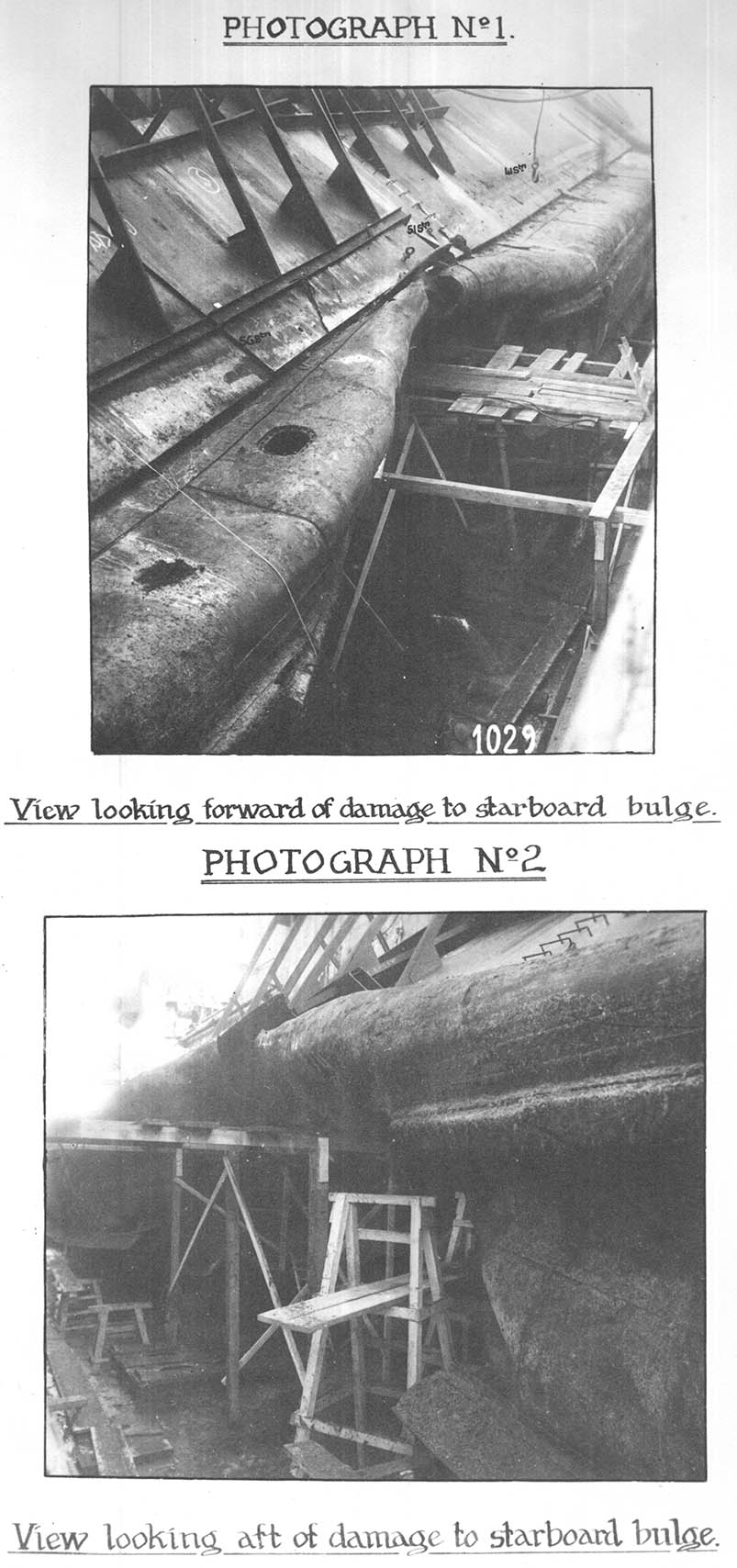
2. (20 lbs. M.S. and 20 lbs. "D") and side framing (6" x 3" x 3" x 17.53 lbs. channel bar) was destroyed over the inner, outer and water jacket compartments. The plating was missing from just outboard of the protective bulkhead, at keel level, up to, but not including, the top strake of the outer bulge. The top strake (30 lbs. M.S.), which extends outboard from the lower edge of the sloping armour, was fractured between stations 52 and 53, heavily buckled and stove inboard (see photograph No. l). 15. Forward to station 45 and aft to station 62, the outer bottom plating (20 lbs. M.S. and 20 lbs. "D") together with the side framing (6" x 3" x 3" x 17.53 lbs. channel bar), from the longitudinal bulkhead at keel level to the lower edge of the sloping armour, was split, buckled and forced inboard. 16. Outside these limits, to stations 39 and 69, the bulge plating (20 lbs. M.S. and 20 lbs. "D") and framing (6" x 3" x 3" x 17.53 lbs. channel bar) suffered minor buckling and distortion. 17. The outer bottom plating (25 and 30 lbs. "D"), between stations 45 and 62 starboard side and inboard from the longitudinal protective bulkhead to within 4 feet of the middle line, was badly corrugated between frames. The bottom framing (3-½" x 3" x 9.02 lbs. angles) and floors (12 and 14 lbs. M.S.) were slightly distorted and riveted connections were strained and leaking. 18. The riveted connections of the sheer strake to the longitudinal protective bulkhead were torn away between stations 47 and 54. 19. The longitudinal stringer (20 lbs. "D" face plate and 20 lbs. "D" side girder), in the outer bulge compartment, was destroyed between stations 51 and 56, and severely distorted and forced inboard between stations 45 and 62. 20. The wooden rubbing strake (9" x 9" elm with 20 lbs. M.S. faoe plate) was missing or wrecked between stations 42 and 62. 21. The bilge keel (35 lbs. M.S.) was destroyed between stations 45 and 54, and suffered damage and buckling to stations 43½ and 62½.Sloping bulge armour and plating under. 22. Between stations 41 and 62 the sloping armour (l60 lbs. N.C.) was displaced and the plating under (20 lbs. "D"), was buckled and distorted. The fracture in the bulge plating, referred to in paragraph 14, continued across this plating, between stations 52 and 53, and extended for the full width of the armour. The connecting angle (7" x 7" x 28.42 lbs. "D") of this plating to the protective bulkhead was displaced between stations 49 and 56 and the rivets had pulled through. 23. The armour was displaced as stated below. (The frame stations referred to indicate the extent of each armour plate).
|
||||||||||||
Longitudinal protective bulkhead. 24. The main longitudinal protective bulkhead (2 in No. thicknesses of 30 lbs. "D. 1" with 10" x 6" x 6" x 40 lbs. "D.l" I bar stiffeners) was dished inboard between stations 48 and 59, as referred to in paragraph 13, but was otherwise not seriously damaged. The structure was strained sufficiently to allow rapid flooding inboard of the protective bulkhead, as described later in the report. (See under Flooding). 25. The displacement of the protective bulkhead was as follows:-
Outer longitudinal bulkhead of water jacket compartments. 26. Damage to the bulkhead plating (12 and 14 lbs. M.S.) and stiffeners (5" x 2½" x 8.5 lbs. T. bar) occurred between stations 39 and 69. 27. Between stations 47 and 60, the bulkhead was destroyed. Forward to station 45 and aft to station 62, the structure was split and severely distorted. Minor distortion and strained connections extended to stations 39 and 69. Inner longitudinal bulkhead of water jacket compartments. 28. Damage to the bulkhead plating (12 and 14 lbs. M.S.) and stiffeners (5" x 2½" x 8.5 lbs. T. bar) occurred between stations 39 and 62. 29. Between stations 51 and 56, the bulkhead was destroyed and missing, and forward, to station 45, the structure was wrecked. Forward of this to station 39 and aft to station 62, the plating and stiffeners were buckled and distorted. Splits occurred in the plating between stations 56 and 62. Main transverse bulkheads. 30. Bulkhead 45 (12 lbs. M.S.) together with its stiffeners (2½" x 5" x 8.5 lbs. T. bar) was severely buckled and distorted from the ship's side to the inner longitudinal bulkhead of the water jacket compartment, and its connections to this bulkhead were torn away. Inboard/.....
|
||||||||||||||||||||||||||||
|
7. 54. Compartments in which Flooding was Controlled.
Total 7 tons per hour 55. The maximum amount of water known to have entered the ship due to damage was about 810 tons. Counterflooding. 56. It is not known when the counterflooding of inner and outer bulge compartments on the port side was stopped, but a total of about 800 tons of sea water must have been admitted to the ship, including 300 tons in the outer bulge compartments and 500 tons in the inner compartments. 57. In addition to the counterflooding, approximately 20 tons of 15 inch shell were moved from the starboard to port shell room. 58. At the time of the explosion the ship was in the Second Degree of Readiness (Relaxed action stations). All valve control positions (V.C.Ps.) were manned but relaxed. The forward and after damage control parties were closed up and dispersed on the Main Deck. All watertight doors and ventilation were in the "Z" state (Action state) excepting the "Z" communicating doors on the Main Deck, which are 'First Gun Doors', the three Main Deck armoured hatches giving access to the forward and after Medical Distributing Stations and the hatch to the Lower Steering Position. The firemain was in the action state, i.e. the forward and aft electrically driven 50 ton hull and fire pumps were connected to the forward and aft sections and the steam driven fire and bilge pumps, in the Engine Rooms, were in use on the centre section. The firemain was isolated at stations 34 and 69. The bulge protection compartments were in the normal Sea or Harbour state, i.e. inner and outer bulge compartments empty and water jacket compartments flooded to within 6 inches of their crowns. All/..... |
|
8. All 550 ton salvage pumps were running on sea suction, with the port and starboard pumps discharging to the 12 inch main suction cross connecting line for the 15 inch Magazine flooding. The state of the main suction line and arrangements for Magazine and rapid flooding were as follows:- All main suction bulkhead valves were shut. The rapid flood 8 inch sectional mains were isolated from the 12 inch main suction line and the isolating valves in each section were shut. The seacocks for the rapid flooding of bulges and those for Magazine flooding were open. 59. When the explosion occurred, at 1703, the pumping and flooding party from the D.C.H.Q. were immediately employed in testing and sounding compartments below the Main Deck. It was found that extensive flooding had occurred within the starboard bulge compartments and, by 1800, it was established that the only serious leakage inside the longitudinal protective bulkhead was between stations 45 and 62 starboard. A fairly accurate picture of the extent of damage was formed. 60. By 1706 water was entering rapidly above the Main Deck through rivet holes, between stations 47 and 56 starboard side. In order to reduce the list and bring these holes above water, an order was given to counterflood the inner bulge compartments on the port side. Pumping of loose water on the Main Deck was also commenced. Attempts to plug the rivet holes in the ship's side between stations 47 and 54 starboard, (see paragraph 18) from outboard proved impracticable, but these were later plugged from, inboard when the list had been reduced. The linings and fittings on the ship's side were stripped as necessary and preparations made for building a cement cofferdam, about 3 feet high, above the Main Deck, along the damaged starboard side between stations 34 and 65. This work was completed in about 12 hours. 61. By 1716, all port inner bulge compartments (stations 21 to 75) were counterflooding and this action appeared to reduce the rate of heel to starboard. 62. At 1720 the list had increased to 10 degrees, the maximum reached, and water was still entering above the Main Deck. Orders were therefore given to counterflood all port outer bulge compartments, stations 21 to 75, and an endeavour was made to pump out the less damaged bulges and water jacket compartments on the starboard side. 63. No. 7 V.C.P., stations 45 to 51 on the Lower Deck starboard side, reported at 1730 that the compartment was leaking and the valves could not be operated due to distortion of the surrounding structure. At 1745 this compartment was temporarily evacuated and closed down. 64. At 1800, 20 rounds of 15 inch shell were transferred from the starboard to port shell room bays. At this period oil was not transferred due to the possibility of air attack and the advisability of keeping the oil fuel filling line empty on that account. 65. By 1900 the list to starboard had been reduced to ¾ degree and the Main Deck cleared of water. 66. The final testing of all compartments was completed by 0500, 10th September, and it was found that shoring of decks or bulkheads was not necessary. Measures were taken by the ship's staff, with the aid of the U.S. Salvage ship MORENO, to prevent the displaced sloping armour on the starboard side being lost. |
|
67. On arrival at Palermo further temporary repairs to structure were carried out and the reclaiming of flooded compartments commenced with the assistance of the U.S. Navy and repair base at Ferryville. 68. There were no fires or incendiary effects as a result of the explosion. Nitrous fumes, with a smell rather like that of flashless cordite, were present in No. 7 V.C.P. and the Lower Steering Position, but were not sufficiently concentrated to necessitate the use of breathing apparatus. 69. At the time of damage all main machinery and both boilers were in use, the units being isolated. The two turbo-generators were on load and the hydraulic engine was idling at immediate notice. 70. When the explosion occurred, steam pressure in the starboard unit dropped 20 lbs. per square inch due to the failure of the oil-fuel pump in the starboard Boiler Room. When the shock and subsequent tremor had died away the pump restarted without attention. 71. Whilst the ship was listed to starboard the lubricating oil in the starboard forward main bearing could not drain sufficiently fast and leaked out at the after end. This cured itself as the list reduced. 72. Whilst in dock, undergoing temporary repairs, it was found that the port propeller shaft could not be turned over approximately 30 degrees. When undocked the shaft could be moved without any undue strain. 73. Various leaks were started in the refrigerating system (Freon) due chiefly to the unusually light gauge of the copper pipes of the cooling circuits (by Naval standards) and the soft soldering of the nipples for the pipe connections. Similar leaks had resulted fron previous gunfire. 74. The fan casing in the starboard Boiler Room was 3/16 inch out of alignment causing it to foul the impellers. 75. All rigid/resilient mountings, holding down arrangements and seatings of main and auxiliary machinery, were carefully examined subsequent to the explosion and none showed any sign of damage or displacement. 76. At the time of the explosion the two 200 K.W. turbo-generators were each supplying its own switchboard. Linking switches at the switchboard were "closed" and inter-connecting switches "open". The remainder of the electrical installation was in complete readiness for an emergency. 77. No generator failures or overloading was experienced when the explosion occurred. 78. Many electric bulbs throughout the ship were damaged, one hundred and sixty eight being found defective after the explosion; of this number only twenty six lamps were situated in the wake of the structural damage. The only section of the ship to suffer a complete failure of lighting from this cause, apart from those damaged by flooding/..... |
|
10. flooding, was between stations 21 and 47 on the Main Deck. The lighting circuits in No. 2 Pump Room, No. 7 V.C.P, and the Main W/T Office were damaged by the explosion, and later by flooding. 79. No. 2-550 ton salvage pump starter casing, in the Pump Room, stations 45 to 51 starboard, was punctured by debris but power was taken off the defective pump and the fuses removed from the main supply at the switchboard before the starter was flooded. 80. Two Mark XV sound powered telephones situated in No. 7 V.C.P., communicating with the D.C.H.Q. and secondary D.C.H.Q. were flooded. 81. The "Sensitive Element" of the forward Master Gyro Compass became detached due to shook and fell on to the deck. The covers of the after Master Gyro Compass mercury contactor were thrown off by shock and the mercury cups emptied. 82. The only other damage to equipment was the fracture of the securing lugs of the "Revo" type overhead fan situated in the Captain's Day Cabin. 83. The 15 inch Director Control Tower was unseated and damaged, and the structure was strapped and shored to obviate the danger of its falling from the fore top. Associated fittings, such as the teeth of the training rack, clips and brackets to the roller path and instruments, were damaged. The live roller ring was distorted, and the flanges of several rollers were crushed and their axes bent. 84. The roof of the 15 inch Spotting Top was distorted and slightly lifted on the starboard side, which possibly affected the easy working of the lower roller path of the Director Tower. 85. The hull structure in the vicinity of the turntable of the 15 inch mounting was distorted, but, so far as could be ascertained, not sufficiently to affect the working of the turret. 86. One of the instruments of the Admiralty Fire Control Table and the Bridge Rangefinder mounting together with its supporting brackets were damaged. The pins of the clutch operating levers of the starboard 4 inch ammunition hoist were sheared and distorted. 87. The base plates of Nos. 5 and 6 twin Oerlikon mountings were strained due to distortion of the Upper Deck in the vicinity. This made training difficult. 88. Equipment of Types 47 and 49 M.R. transmitters in the Main W/T Office was damaged by shock. 89. Water leaked into the Main W/T Office from the flooded Main Deck above through the gland of a pneumatic tube, and flooded the Sound Reproduction Equipment transfomer, causing the supply switch to the pneumatic tube to burn out. 90. In No. 7 V.C.P., the motor alternator and all batteries of the emergency supply of Type 406 warning telephone, together with other electrical equipment, were rendered useless by flooding. 91./.... |
|
11. 91. On No. 1 Platform shock damage was sustained by Types 86, 87 and 89 W/T sets. 92. The port inner leg of the main W/T aerial was brought down by the shearing of the riveted connections of the arm holding the aerial from the ship's side. The protective loops functionel correctly. 93. Shock damage was also sustained by Types 272 and 281 Radar sets. The aerial poles of the Type 281, transmitter and receiver, were slightly bent and valves and other equipment were damaged. This damage was of a minor nature however and within two hours of the explosion Type 272 was functioning correctly. 94. The securing bolts of the A/S amplifier, situated in the Chart House, were sheared by shock, and the secondary winding of the transformer and all valves were broken. 95. The cast iron supporting columns of the potato peeling machine were fractured. 96. No damage occurred to the Sick Bay, Distributing Stations or First-Aid Posts. 97. The fact that the ship was at relaxed "Action Stations" and the majority of the ship's company were sitting or lying down at their stations, when the explosion occurred, no doubt accounted for the small casualty list, bearing in mind the force of the explosion and the amount of debris which fell on the deck. 98. Casualties;- One rating had a broken arm and 7 others had minor cuts and bruises. 99. The desirability of siting First-Aid Posts, manned by trained personnel under a Sick Berth Attendant, within easy reach of Upper Deck personnel exposed in action, was clearly demonstrated. None of the injured had to walk, or be carried, more than five yards and the possibility of aggravating injuries by unskilled transportation was therefore eliminated. XV EFFECT ON FIGHTING EFFICIENCY. 100. Indirect bombardment could not be continued, as the 15 inch Director Control Tower was unseated and no alternative arrangements are provided. The turret could have been fired but increased damage to the surrounding ship's structure would probably have resulted. 101. Type 281 Radar, for aircraft warning, was out of action as a result of all valves being broken in the set. Commanding Officer. 102. "The ship was listed, to port so as to reduce the level of water in No. 7 V.CP. and so enable the door to be opened and a more exact examination/..... |
|
12. examination and repairs to be carried out in this compartment and in the Pump Room below. A portable pump was used to pump out the last foot of water in the valve control position, the main part of it having been allowed to drain down into the Pump Rocm through the damaged deck. If a high sill had been fitted in the doorway of the V.C.P., it would have been a simpler matter to empty the compartment without causing a small flood across the Lower Steering Position deck." Admiralty Comment. 103. The watertight door to No. 7 V.C.P. is 5 feet 6 inches by 3 feet to permit the passage of a 550 ton pump. No objection is seen to fitting portable watertight sills, 2 feet 3 inches high, to the port and starboard V.C.Ps. (Nos. 6 and 7) as this pump will ship through a 3 feet by 3 feet opening. The Commanding Officer has been authorised to take action accordingly. Commanding Officer. 104. "Considerable unnecessary damage to equipment, notably in the Wireless Office, was sustained because of leakage of water between the Main Deck plating and the armour supported by it. The reason for this is that though the deck glands for valve rods, electric leads etc. prevent water above the armour leaking through into spaces beneath the Main Deck (and such spaces will give satisfactory results under the standard air pressure test), no glands are fitted on the under side of the Main Deck plating. It is recommended that some arrangement be made, either to ensure watertightness between such deck plating and the armour bolted to it, or else that glands be fitted both on the upper and lower sides where any shafting, lead or pipe passes through an armoured deck." Admiralty Comment. 105. The deck plating under the armour, in way of gear rods, pipes, etc. should have been cut back from the hole, the plating tap riveted to the armour and caulked at the edge of the hole against the armour. The Commanding Officer has been authorised to take action accordingly. Commanding Officer. 106. "It is desired to draw attention to the vulnerability of the long lengths of 8 inch rapid flooding lines which pass through the inner bulge compartments together with their valves and the rod gearing in connection with them. From the sole consideration of the security of these flooding lines and their valves, it would be advantageous to keep them all within the ship's main protective longitudinal bulkheads as, for instance, is the case with the main 12 inch suction system. If this were done it would be necessary to pierce the main longitudinal bulkheads at many points in order to carry the suction pipes to the individual bulge compartments and would also result in weakening the main longitudinal bulkheads. It is for consideration whether these disadvantages are acceptable. It/..... |
|
13. It is felt, however, that future construction night be improved by:- (1) Increasing the scantling of the outer longitudinal bulkheads of the inner (air space) bulges so as to afford greater protection for the valves, gearing and rapid flood mains within the inner bulge compartments. (2) The 8 inch lines with their valves, gearing etc. being kept as close as possible to the main protective longitudinal bulkheads and strongly supported from them." Admiralty Comment. 107. To arrange the 8 inch rapid flooding main on the inboard side of the longitudinal protective bulkhead would involve piercing this bulkhead about 1+ feet above the inner bottom level for each of the 29 watertight compartments in the bulge. This would prejudice the watertight integrity of the ship and the disadvantages are not acceptable. (1) For the "Sandwich" form of underwater protection, experiments have shown that the longitudinal bulkheads of the water jacket should be of comparatively light scantlings to give maximum protection. To fulfil their function of spreading the force of the underwater explosion, they should collapse without rupturing or unduly deforming the structure to which they are secured. (2) From information available at Admiralty the 8 inch pipe lines have been worked to the scheme suggested in order to obtain "easy" bends and were also arranged as low as possible, apparently secured to the brackets at the feet of the protective bulkhead stiffeners. Commanding Officer. 108. "The means of establishing the extent of the damage to and flooding of the bulges is very slow and it is suggested that the fitting of distant reading gauges of the type used for feed tank level recording in modern construction Engine Rooms would bo an improvement. The method of ascertaining the depth of water in bulge compartments in ABERCROMBIE is by 'dipping' with long and cumbersome linked steel rods. On this occasion a number of the sounding tubes were so broken or distorted that no sounding could be taken. The only method of ascertaining whether a bulge contains water or not is by taking a suction on the compartment concerned with a salvage pump. If the pump loses suction within half an hour or less, the flooding can be assumed to be controllable, but only one compartment at a time can in this way be tested with one pump. In the case of 1.17, 1.19, W.15 and O.15 bulge compartments there was no method of ascertaining the extent of flooding as their sounding tubes were distorted and no suction could be put on them owing to "M" seacock (open in action) having been damaged and jammed in the "Open " position. In order to connect these compartments to the 12 inch main suction line it would have been necessary to open valve L.13 and the main suction line would then have been open to the sea through "M" seacock. If any, of these compartments were empty the result would merely have been to flood it. The/..... |
|
14. The state of the above compartments remained in doubt until the opportunity dame for divers to blank "M" seatube." Admiralty Comment. 109. In August 1940 the provision of depth indicators for ROBERTS was discussed and a decision, also applicable to ABERCROMBIE, was made not to fit these indicators. Depth gauges were omitted at the time of construction to economise time and labour. It is now considered that depth indicators are desirable for rapid flood and water protection compartments in the bulge, port and starboard, and the Commanding Officer has been authorised to take action accordingly. Commanding Officer. 110. "Under the stress of emergency the disadvantage of having the working positions of many important valves concentrated in the two large valve oontrol positions (Nos. 6 and 7 V.C.Ps, - 45 to 51, P. and S.) became very apparent." Admiralty Comment. 111. The valve control positions (V.C.Ps) for rapid flooding of the bulges were arranged for the convenience of the Damage Control parties and under the protection of armour. In view of the inadequate Damage Control Complement carried by the ship greater efficiency would not be obtained by further separation of the handwheels and an alteration is not considered desirable. Commanding Officer. 112. Flooding Board. "This was of great assistance. It could, however, be improved by the addition of a midship section mounted on it and pivoted at approximately the normal centre of buoyancy, marked off in degrees (port and starboard from the centre line) and with a fixed horizontal line to represent the ship's normal D.W.L. When necessary, the section could be tilted to the angle of list taken up by the ship and thus afford a visual "ready reckoner" which would be of great assistance in the quick determination of the position of compartments relative to the water line with list on the ship. Attention could then be concentrated on compartments in danger of flooding. In these circumstances it is very difficult to form an accurate mental picture of the situation". Admiralty Comment. 113. The addition to the "flooding board of a pivoted midship section would give an approximate picture of immediate flooding and no objection is seen to its adoption by Ship's Staff but it should be borne in mind that Flooding Boards are not usually drawn to scale. Commanding Officer. 114. The entry of water above the Main Deck, its rapid longitudinal spreading and the necessity for building cofferdams along part of the Main Deck level draw attention to the following:- (l) The ever conflicting issue of ship's side lining from the point of view of habitability of living spaces as against inaccessibility of damage. |
|
15. (2) Athwartship bulkheads of cabins, offices etc, on the Main Deck, which are not intended to form main watertight bulkheads should, nevertheless, be made watertight from the deck up to a height of at least 4 to 5 feet in order to prevent, or at any rate retard, the longitudinal extension of flooding along this deck. (3) Longitudinal dwarf bulkheads should be built on the Main Deck, port and starboard sides, to confine the effects of flooding in circumstances such as have been described." Admiralty Comment. 115. (l) For reasons of habitability it was decided that all linings to ship's side must be retained except in the case of Capital Ships, Aircraft Carriers and Cruisers in which they are to be removed only in the vicinity of the waterline - C.A.F.O.1665/40 refers. (2) and (3). No objection is seen to this proposal and where practicable the work should be carried out in order to break up the fore and aft deck spaces into about 16 feet lengths. For guidance C.A.F.O. 2472/42 and A.F.O.4479/43 refer. The Commanding Officer has been authorised to take action accordingly. Commanding Officer. 116. "It is desired to draw attention to the fact that the ship was designed to have no trim and to float at approximately 14 feet 6 inches, D.W.L. In practice the ship has always had a 3 foot trim by the stern, the average draught being in the neighbourhood of 12 feet 9 inches forward and 15 feet 9 inches aft." Admiralty Comments. 117. The Monitor ROBERTS was designed to float at a level draught of 12 feet. Modifications and additions resulted in a final condition which gave a trim of 23½ inches aft in the deep condition. This was accepted and considered preferable to an even keel. ABERCROMBIE was built as a repeat of ROBERTS and thus started life with trim and additional draught. Commanding Officer. 118. "Any heavy explosion at the base of the bulges is likely, owing to the impossibility of 'venting', to displace the sloping armour, and thus tear out the rivets securing the armour to the ship's side. With heel on the ship, the conditions of flooding described are inevitable and, in a rough sea, might be sufficiently aggravated to be extremely serious". Admiralty Comment. 119. Experiments and war experience have proved that damage to structure is not reduced by the fitting of vent plates in the underwater protection and the provision of these plates has been discontinued. Some displacement of armour in the wake of damage must be accepted. Commanding Officer. 120. "With the exception of the lack of electric welding equipment (see paragraph 124) and pneumatic drilling outfit, the stores for Damage Control purposes were adequate. A/.... |
|
16. A pneumatic drilling outfit would havo assisted greatly in making the holes in the deadlights besides conserving the stock of Oxygen and Acetylene gases, which are not in plentiful supply. It is considered that a ship of this class should be supplied with a pneumatic drilling and hammer outfit." Admiralty Comment. 121. It is under consideration to supply pneumatic tools and to fit a low pressure air system, independent of the existing high pressure air system and embodying an electrically driven air compressor and an air receiver. Commanding Officer. 122. Portable Pump Suction Strainers. "Those are not very satisfactory because they lose suction in a depth of water less than about 4 inches due to air being drawn in through the uncovered holes in the top surfaces. This condition could be improved if the strainers were flat bottomed having holes in the bottom surface only instead of, as at present, with holes in all surfaces". Admiralty Comment. 123. The low level strainer as supplied with the electrically driven portable pump consists of a perforated outer casing and a plain inner raising open at the bottom. It is designed to clear water from the compartment down to approximately 3/8 inch. In use the strainer should be horizontal, when, although the upper perforations of the strainer become uncovered air cannot enter the pump due to the plain inner casing. It would appear that in ABERCROMBIE the strainer was tilted from the horizontal thus allowing air to enter the pump through the bottom of the inner casing when the depth of water was 4 inches. A strainer as proposed by the Commanding Officer would be more unwieldy and less efficient than the existing one. Commanding Officer. 124. "It was extremely fortunate that the ship was in company with the U.S. Salvage Section who were helpful in providing equipment we lacked, such as welding sets, which were invaluable in expediting the preliminary arrangements for securing the sloping armour. It is considered that a ship of this class should be supplied with electric welding equipment". Admiralty Comment. 125. The supply of one portable electric welding set to Monitors has now been approved. Commanding Officer. 126. Damage Control Communication System. It is desired to stress the following points:" (1)/.... |
|
(1) No sound powered telephone in the system failed, not even the one fitted in the Valve Control Position which became flooded. (2) It is very necessary for a telephone to be fitted between the Bridge and the Secondary D.C.H.Q. in order to enable the Damage Control Officer to speak directly with the Captain (to keep him informed of the position between decks, etc.) and so avoid the waste of time involved in going up to the Bridge, or the risk of a misinterpreted message being passed through a third person. The Action Damage Control Officer stationed in the Damage Control H.Q. on the Lower Deck can talk directly with the Captain, but the Damage Control Officer (the Engineer Officer based in the Secondary D.C.H.Q., vide C.A.F.O. 51/43, paragraph 4, on the Main Deck) cannot telephone to the Bridge as there is no telephone between the Main Deck and the Bridge. A further point (one that was not brought to light on this occasion of receiving damage and could not, apparently, be rectified during the building of the ship owing to the late arrival of the plans for the telephone systems) is that the hand sets for a number of the Valve Control Positions are sited in positions above the Armoured Deck instead of at the positions below it from which the valves are actually worked. Thus, telephone messages to these positions must be passed by the telephone number, entailing the opening up of the requisite armoured hatch for the purpose. It is considered that the following additional telephones are therefore required for essential "Damage Control" communications.
Add/.....
|
||||||||||||||||||||||||||
|
|
SOURCE:
National Archives & Records Administration, College Park
Record Group 19, US Navy Bureau of Ships Records Relating to Foreign Ships & Ordnance
Transcribed by RESEARCHER @ LARGE. Formatting & Comments Copyright R@L.