If you can see this text here you should update to a newer web browser
Normal | Highlight & Comment Highlighted Text will be in Yellow
|
|
|
|
TABLE OF CONTENTS
(III) I stole this from Researcher@Large! |
||||||||||||||||||||||||||||||||||||||||||||||||||||||||||||||||||||||||||||||||||||||||||||||||||||||||||||||||||||||||||||||||||||||||||||||||||||||||||||||||||||||||||||||||||
|
IV
January 1943
I stole this from Researcher@Large!
|
||||||||||||||||||||||||||||||||||||||||||||||||||||||
|
(VI)
|
|
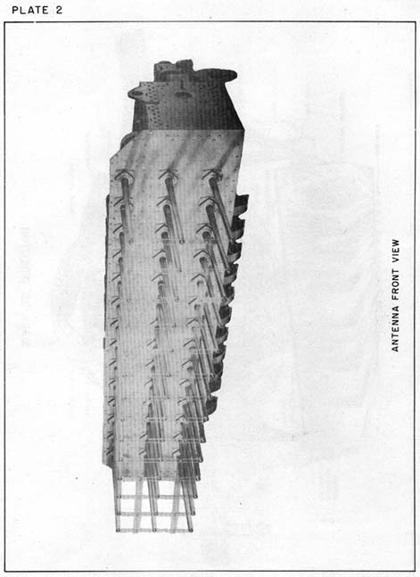
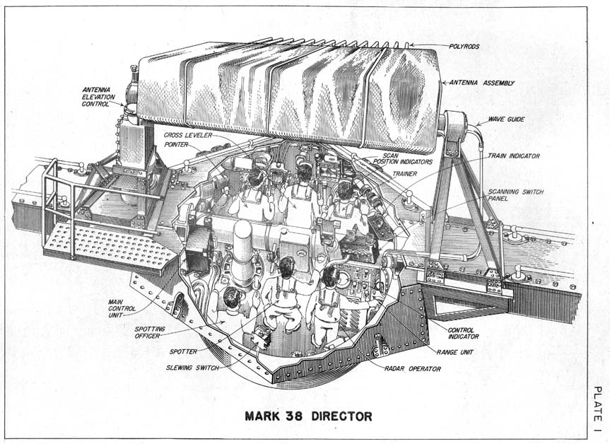
FIRE CONTROL EQUIPMENT — FIRE CONTROL RADAR, MARK 8 — 1. The Mark 8 Radar is a main battery fire control equipment designed for use with Mark 34 and Mark 38 directors. Briefly, its basic principle of operation is as follows: A narrow beam (6° vertically and 2° horizontally) of radio energy in the form of short pulses is radiated from a "polyrod" antenna. Upon striking an object some of this energy is reflected and an "echo" is picked up by the receiver. This echo is indicated on the screens of the indicators as either type A or type B scan. The operator then makes easy and rapid adjustments of the controls to obtain the range and bearing of the reflecting object. Range and bearing are transmitted to plot and used in the solution of the fire control problem. 2. Some of the important characteristic properties of the Mark 8 Radar are as follows:
(1) I stole this from Researcher@Large! |
|||||||||||||||||||||||||||||||||
|
2
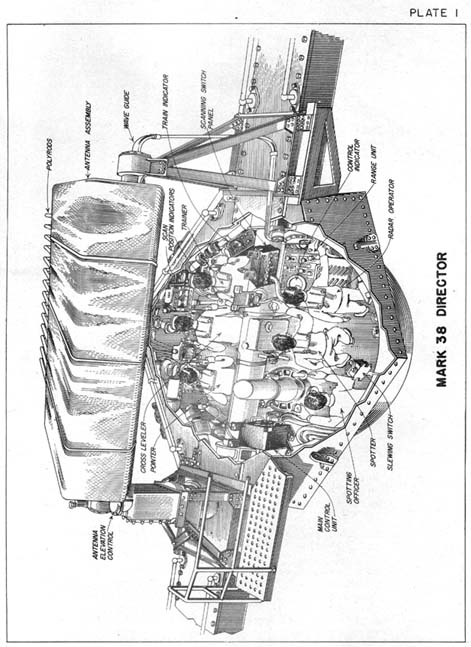
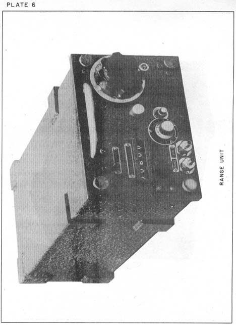
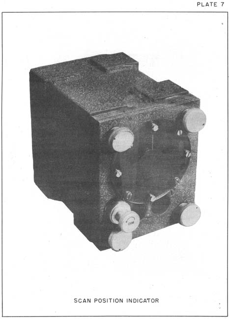
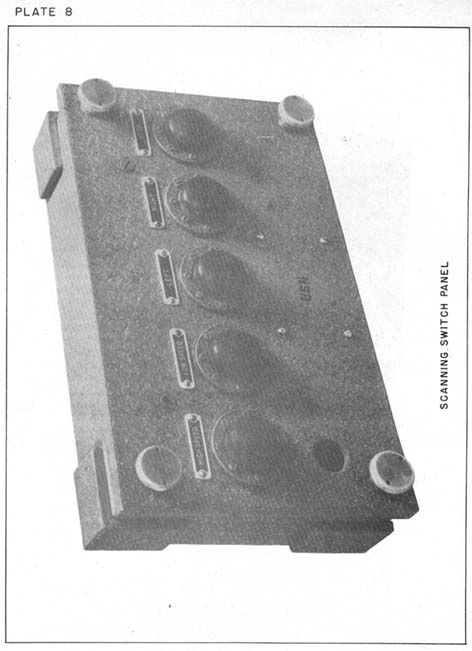
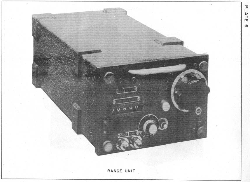
3. Before considering details of operation the operator should have a clear picture of the radar system as a whole and should know the names, locations and functions of the principal units of the equipment. The following brief outline, if studied carefully with the aid of the accompanying cutaway drawing of the Mark 38 Director (see pl. 1), should establish the interrelationship of the main parts of the apparatus and form a basis for an understanding of its effective operation. Positions noted in parentheses are for the Mark 38 Director, but in most cases also hold for the Mark 34 Director.
|
||||||||||||||||||||||||||||||
Rotated Version of the below image
|
(3) |
Rotated Version of the below image
|
(4) |
Rotated Version of the below image
|
(5) |
|
(6) |
|
7
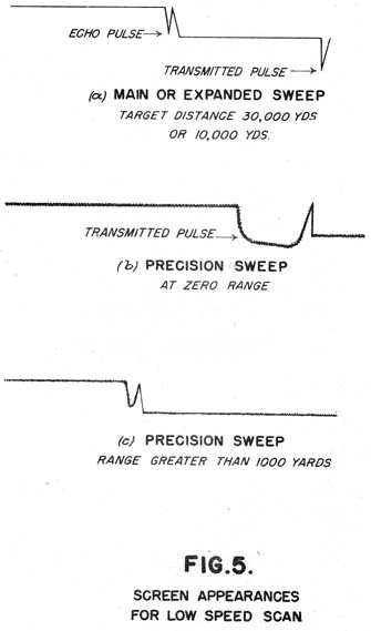
DATA PRESENTATION AND INTERPRETATION 4. There are two general methods of presenting the data or, in other words, showing the location (range and bearing) of the target. These two methods are:
|
|||||||||||||||||||||||||||||||||||
|
8 5. In both methods (a) and (b) the operator has a choice of three range sweeps: (a) MAIN sweep, 6. In MAIN sweep the screens indicate ranges from 0 to 60,000 yards. In EXP sweep they go from 0 to 20,000 yards. In PREC sweep any range interval of 2000 yards may be indicated as long as the interval lies between 0 and about 45,000 yards.
|
Rotated Version of the below image
|
(9) |
Rotated Version of the below image
|
(10) |
|
(11) |
Rotated Version of the below image
|
(12) |
|
13
|
|||||||||||
|
15 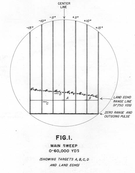
|
|
16 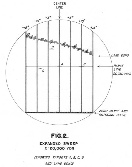
|
|
17 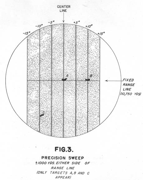 I stole this from Researcher@Large!
|
|
18 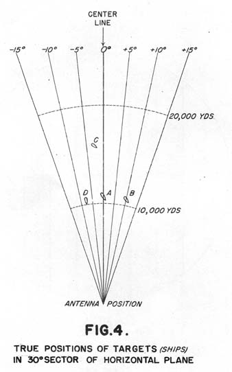
|
|
19
|
||||||||||||||||||||||||||||||||||||||||||
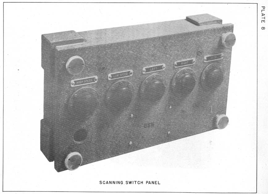
NOTE: Except for minor adjustments which may improve performance the equipment is now ready for measurements at High Speed Scan and PREC sweep. The series of operations above need not be repeated, however, if the operator wishes to use a different scan or sweep. Switches are provided on the Control Indicator and Scanning Switch Panel for quick changes from one type to another. However, IN SWITCHING FROM LOW SPEED TO HIGH SPEED or VICE VERSA ON THE SCANNING SWITCH PANEL TWO PRECAUTIONS should always be taken to avoid damage to the equipment. Make sure that SCAN SWITCH on C and I is on LOW SPEED. Always push STOP BUTTON ON SCANNING SWITCH PANEL. - - - - - - - - - - - - - - - - - - - - - - - - - - - - - - - - - - - - - - - - - -
|
||||||||||||||||||||
|
21
|
|
22 
|
|
||||||||||||||||||||||||||
|
24 9. A general idea of methods employed in obtaining and interpreting data has already been given in the section on Data Presentation and Interpretation. Solution of the fire control problem for a surface target requires such accurate determinations of range and bearing, however, that those instructions will be continued here.
(b) To obtain Bearing of Target
|
||||||||||||
|
25
|
||||||||||||||||
|
26 10. A few notes on performance are given below. I stole this from Researcher@Large!
|
||||||||||||||||||||||||||||||
|
27
|
||||||||
|
D I S T R I B U T I O N Ordnance Pamphlet No. 658 has been given the following initial distribution:
* Anacostia - 50 I stole this from Researcher@Large! Notification of any desired changes in the above distribution should be forwarded directly to the Bureau of Ordnance. Requests for additional copies of this Ordnance Pamphlet should be made directly to Naval Gun Factory, Washington, D. C., the Navy Yard, Mare Island, California, or Navy Yard, Pearl Harbor, T.H. |
SOURCE:
National Archives & Records Administration, San Francisco
Pearl Harbor Navy Yard General Correspondence 1941-45
Transcribed by RESEARCHER @ LARGE. Formatting & Comments Copyright R@L.