
If you can see this text here you should update to a newer web browser
Normal | Highlight & Comment Highlighted Text will be in Yellow, but there are none yet
|
|
|
Handbook on Ship Camouflage CandR-4.
Navy Department Bureau of Construction and Repair 1937
|
|
CandR-4 Handbook on Ship Camouflage Navy Department,
1. CandR-4 is a confidential registered publication which has been prepared for information and guidance in connection with the preparation of camouflage designs for surface vessels. 2. Attention is invited to RPS-4, Article 219(d). IT IS FORBIDDEN TO MAKE EXTRACTS FROM OR TO COPY THIS PUBLICATION WITHOUT SPECIFIC -AUTHORITY FROM THE CHIEF OF NAVAL OPERATIONS; EXCEPT AS PROVIDER FOR IN ARTICLE 219(d), OF THE CURRENT. EDITION OF THE REGISTERED PUBLICATION MANUAL. 3. CandR-4 shall be handled, and it shall be accounted for direct to the Chief of Naval Operations (Registered Publication Section), in accordance with the instructions contained in the Registered Publication Manual and the Navy Regulations. 4. The methods of transportation authorized for CandR-4 are contained in Navy Regulations and the Registered Publication Manual. 5. It is not intended that this publication be carried in aircraft for use therein. 6. When not in actual use CandR-4 shall be stowed in a Class B stowage as defined in the Registered Publication.Manual.
W. G. DuBOSE,
I |
|
TABLE OF CONTENTS (Continued)
9. MISCELLANEOUS CAMOUFLAGE.
III
|
|
TABLE OF CONTENTS (Continued)
IV
|
|
(c) Dazzle camouflage by means of paint. A ship is painted with colors and patterns to produce effects of confusion or deception as to its course in order to disturb estimation of target angles by an enemy. (d) Camouflage bv structural design. Superstructure details are designed, or changed in design, in order to disturb estimation of target angles. (e) Miscellaneous camouflage includes: painted water line and bow wave, painting a ship to look like another ship, use of luminous paint, artificial lighting, small pattern, counter-shading, etc. Aspects of camouflage not discussed in the handbook are low visibility painting of submarines, reduction of visibility of the periscope feather, secret painted identification insignia and smoke screens.
2
|
|
2. REFERENCES AND HISTORY
References. The handbook is based on the following sources of information, which are believed to include all available data: (a) "The Development of Marine Camouflage and Tests Relating Thereto," by Harold Van Buskirk, Lieut. (CC) U.S.N.R.F., May 1, 1919. BuC&R file 14258-A14, enclosure (A) with Vol. 4. (b) Ibid., enclosure (B) with Vol. 4. (c) Ibid., enclosure (C) with Vol. 4. (d) "Marine Camouflage," May 10, 1920, BuC&R file 14258-A14, enclosure (A) with Vol. 5. (e) A large number of World War dazzle camouflage designs stored at the Naval Torpedo Station, Alexandria, Virginia. (f) Naval Research Laboratory Report No. H-1196, "Preliminary Report on Low Visibility Camouflage of Ships," September 18, 1935.
(g) Naval Research Laboratory Report No. H-1239, "Camouflage of Naval Ships, Tests at Sea of November and December, 1935," February 21, 1936.
3
|
| *NOTE* The below are inks printer on paper and should not be used as an authoritative source for color matching of paint. |
|
CAMOUFLAGE COLORS
PLATE I
|
|
surfaces should be a very dark gray or nearly black, and vertical surfaces considerably darker than Standard Navy Gray; that for low visibility to surface observers in clear weather, vertical surfaces should be considerably darker than Standard Navy Gray, and in overcast, hazy or foggy weather, should be Standard Navy Gray. Specific experiments were recommended which were carried out in November and December, 1935, by Destroyer Divisions in the San Diego area. The experiments and results, reported in reference (g), sub-stantiated in the main the conclusions of reference (f). In the case of dazzle camouflage, a survey was made in 1936 of the earlier literature of the first five references. New dazzle designs were worked out and tested on small models of ships in the laboratory, but none was tested on ships at sea. The investigation was described in reference (h).
5
|
|
The formulae for the respective colors are: Quantities for 10 gallons.
Although these camouflage colors have been specified with exactness the question arises whether exact reproduction of the colors is necessary or of any consequence. There are no clear cut experimental data on which to base an answer to the question. However, it may be supposed that slight departures from the specified shades would be of negligible importance, since camouflage has to meet so many different and uncontrollable conditions that it is not an exact science, and since any shades of color no matter how carefully - - - - - - - - - - - - - - - - - - - - - - - - - - - - - - - - - - - - - - - - - - - - - 7
|
||||||||||||||||||||||||||||||||||||||||||||||||||||||||||||||||||||||||||||||||||||||||||||
| Click here for a larger, rotated version of this plate. |
|
|
| Click here for a larger, rotated version of this plate. |
|
|
| Click here for a larger, rotated version of this plate. |
|
|
|
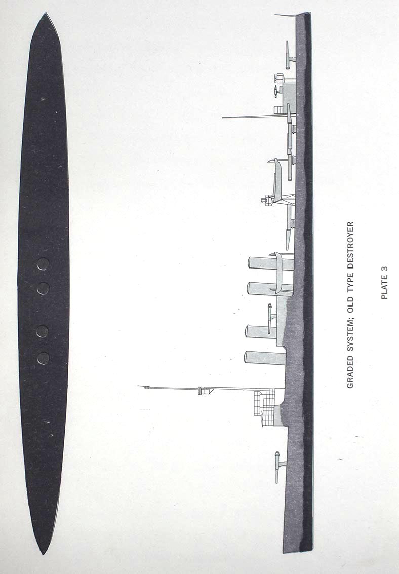
Camouflage experiments by Destroyer Divisions Five and Eighteen in the San Diego area during November and December, 1935, reference (g), led to the following conclusions: (1) In clear weather in the day the Ocean Gray and the Graded systems were less visible than the standard Navy Gray system; no comparisons of the Ocean Gray and the Graded systems were made, and their relative effectiveness is not known, (2) In cloudy weather, haze and fog in the day the standard Navy Gray system was the least visible of the three systems, (3) At night under natural illumination there was little difference between the three systems, (4) At night under searchlight illumination black was of lower visibility than any of the three systems. In general, each of the conclusions was based on a single experiment which consisted in painting one destroyer in a prescribed manner and in observing the effect from several ships and airplanes over a period not longer than a few days. The conclusions, although clear and definite, therefore require substantiation by further experiments with several ships of various types over extended periods of time, wide areas of sea and various conditions of weather.
11
|
|
It is to be noted that the conclusions were mainly qualitative; few quantitative data were presented concerning the visible ranges of the three systems under various conditions of light and weather.
12
|
| Click here for a larger version of this plate. |
|

|
|
which depend upon an ingenious use of pattern to give the impression of a course quite at variance with the true, course. All good designs of the latter group rely upon a distortion of perspective or an apparent alteration of form to achieve the desired result. "All distortion as to course is lost when the design is viewed from above* This was one of the reasons why dazzle camouflage was not applied to the battleships* Its chief value is as a defense against submarine attack where the enemy point of view is low. "In the first American designs the aim was to give the maximum course distortion possible, and to create the il-lusion that the vessel was steering as much as 90 off her true course, but the later tendency was to strive for a more modest distortion, and one which would be effective during a longer period of time.if Designs of the first type were apt to be weak when the vessel was seen very nearly bow on, and when seen three or four points off the bow the change in the apparent size of the vessel would in a short time possibly give the lie to the deception caused by the design. "The best designs were those which were capable of a double interpretation, and would leave the observer in doubt as to whether the approaching vessel would pass on his starboard side or would be well over to port.
16
|
|
"When the British abandoned the large patterned camou-lage altogether and went over to the use of stripes entirely, one of the other countries followed the example. Our first striped design, Type 3, Design C, was produced in April, 1918, and was issued to the Shipping Board on May 13, before the British had gone over to the 1 zebra' type of design* With many variations we utilized this same stripe motive in a large number of subsequent designs, but it was never deemed advisable to abandon all other types of design in its favor. It is perhaps worthy of note that Lieutenant-Commander Wilkinson particularly commended our Type 5, Design C, and spoke of it as the best of our designs* (William Andrew Mackay's report to the United States Shipping Board* London, November 14, 1918*) "We reached conclusions different from the British in regard to the use of verticals in dazzle designs* The fear of vertical lines has been one of the current superstitions prevailing throughout all of the brief history of marine camouflage* In the early stages it was customary to claim that this or that type of design 'destroyed vertical lines and thereby rendered range finding more difficult.1 Design schemes involving the use of vertical lines were instantly rejected by persons who might have been supposed to be in possession of accurate information. And yet all the time camouflage was being considered primarily as an anti-submarine device, and there was no reason to suppose
17
|
| Click here for a larger, rotated version of this plate. |
|

|
| Click here for a larger, rotated version of this plate. |
|

|
| Click here for a larger, rotated version of this plate. |
|

|
| Click here for a larger, rotated version of this plate. |
|

|
| Click here for a larger, rotated version of this plate. |
|

|
|
nature, and of this number 193 had been made for Navy-vessels and 308 for the United States Shipping Board vessels. In the Naval Torpedo Station at Alexandria, Virginia, are collected a large number of dazzle designs, reference (e). It is believed, but is not known with certainty, that these are some or all of the 495 mentioned above. The designs employ black, grey, gray white, greenish gray, blue and yellow colors. Each design was apparently prepared for a particular ship as designated on the drawing. In order to examine the effect of the designs, five were selected at random, and were painted on a 14-inch model with approximately the specified colors. Black and white reproductions of the five designs and photographs of the model painted with the designs are shown in Plates 6, 7, 8, 9 and 10. When the model was viewed in the Laboratory theatre it was seen that the designs in general produced no marked course distortion but gave the effect of course confusions or uncertainty. They appeared to be very successful designs from this standpoint. It is not known how these designs were arrived at, nor is there any statement in the references to indicate the experimental method used by the subsection of Design in developing and testing the designs. True, an elaborate theatre was built for the purpose of testing the designs on small ship models, as described in reference (c), but it was
19
|
|
the attacking submarine commanders." "In the case of vessels of the fleet it was established that dazzle painting would he objectlonalbe for vessels in the line."
22
|
|
"unobtrusive" designs. The obtrusive design endeavors to produce the deception by a bold and distinct pattern. The observer therefore perceives immediately that the ship is painted in an unusual way and may be expected to infer that the painting is for the purpose of delusion. The unobtrusive design aims to produce the deception by a pattern which is not noticeably unusual. In this case, if the design is successful, the observer is deceived as to the course of the camouflaged ship and is ignorant of the fact that he is deceived. No evidence could be discovered that colors add to the effectiveness of the designs, and therefore all the new designs presented here employ only the three shades of gray which are shown on Plate 1. The shades used in the designs of Plates 11 to 22 are evident from an inspection of the plates* White would be a useful color but is avoided, perhaps unnecessarily, because of the increase in visibility which it might occasion at times. The following general remarks may be made regarding course distortion design: (a) All course distortion designs depend on painting a pattern of distorted perspective on the sides of the ship. (b) The distortion of perspective must neither be too slight nor too extreme.
24
|
|
(c) Distortion of perspective such as to make the stern appear nearer and the how farther than is actually the case is more successful than that which pushes the stern away and brings the bow nearer. In other words, perspective distortion which twists the course of the ship away from the observer is more effective than distortion which twists the ship toward the observer. This is particularly true for ships with pronounced sheer. (d) The superstructure may be painted either with bold pattern to give a confusing effect or with a purposefully chosen pattern to supplement the distortion design on the hull. (e) Course distortion may be achieved by treating only the hull and leaving the superstructure untouched, or by treating only the superstructure and leaving the hull untouched; but when both are treated the combined effect is much more convincing than the sum of the two effects taken separately. (f) Although in general any design is applicable to any type of ship, advantage may be taken of structural characteristics to improve the details of the design. It is best therefore to consider each type of ship separately and
25
|
|
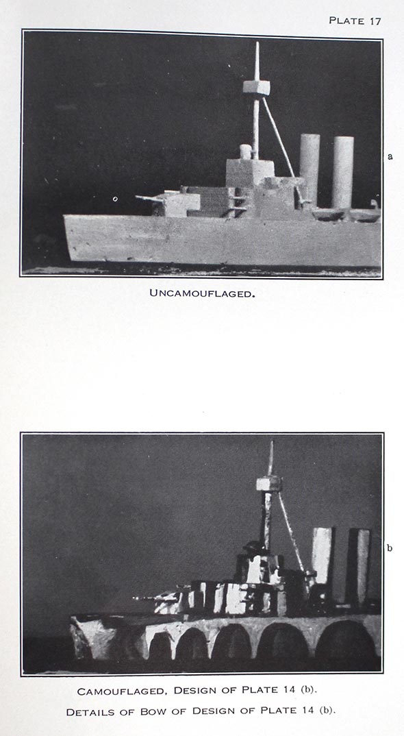
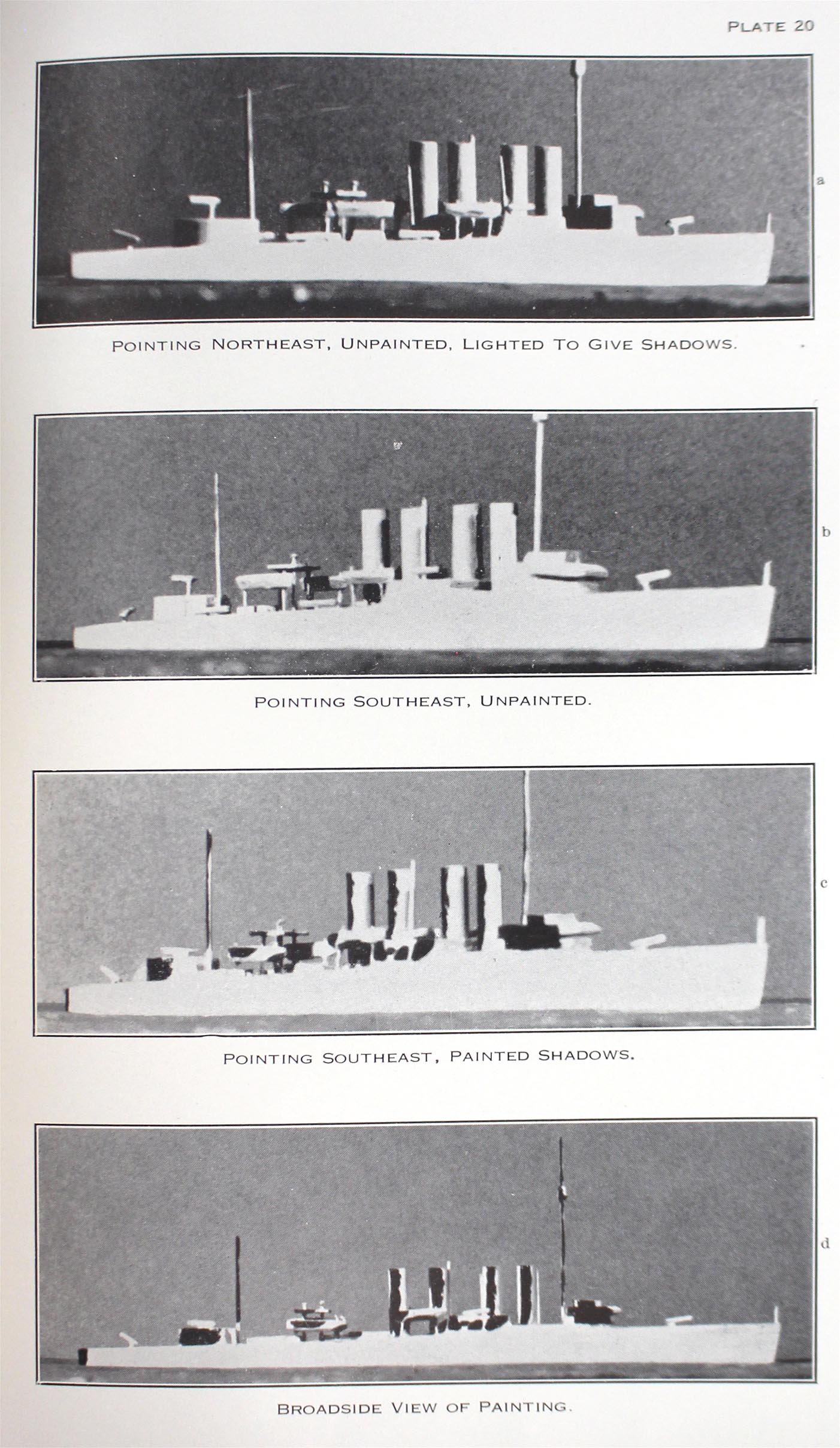
An effective course distortion design for the superstructure is given in Plate 18d. The method of obtaining the design consisted in observing the prominent shadows in the superstructure when the ship is heading away from the observer and painting these shadows on the superstructure when the ship is heading more or less toward the observer. The various steps are illustrated in the pictures of Plates 18a, b and c, which refer to the observer looking North. Plate 18a is the unpainted ship pointing northwest and lighted by a western sun to give shadows. Plate 18b is the unpainted ship pointing southwest. Plate 18c is the camouflaged ship pointing southwest. Plate 18d is a broadside view of Plate 18c. In the case of a real ship underway at sea the false painted rudder, seen clearly in Plate 18d, may rarely be visible and therefore of little importance. The design of Plate 18 is open to an interesting criticism. Suppose that the situation of Plate 18c occurred, that is, that the observer was looking north at the ship actually heading southwest. Due to the painted shadows, however, he would be deceived into thinking that the ship is heading roughly northwest. Assume now that the sun was to the east; the ship would be well illuminated to produce the desired deception. A moment's reflection on the part of the observer would convince him, however, that an easterly
27
|
|
sun could not possibly produce such shadows on a ship which he supposed was moving in a northwesterly direction. He might therefore conclude that the shadows must be fictitious, that the ship was camouflaged and that his impression of a northwest course of the ship was erroneous. The superstructure design of Plate 18 may be used in whole or in part with any of the hull designs of Plates 11 to 15 which are of such a nature that they do not interfere vith the superstructure design; it is in fact used on the designs of Plate l1b and Plate 12b. The design of Plate 18 consists of dark painting on a light background. The converse design of light painting on a dark background is equally effective; such a design is shown in the pictures of Plates 19a and b, which again refer to the observer looking north. The superstructure design of Plate 18 is most effective on types of ships with prominent and simple superstructures. It was less successful on a model of a destroyer, because the destroyer superstructure had no large unencumbered areas of shadow. The various steps in putting the design on the destroyer model are illustrated in Plate 20. An illustration of an unsuccessful course distortion sign is given in Plate 19c. The bow design is too extreme and too complex; it is inconsistent with the stern design. When the model was heading toward the observer the design produced confusion and from this standpoint was successful.
28
|
| Click here for a larger version of this plate. |
|

|
| Click here for a larger version of this plate. |
|

|
| Click here for a larger version of this plate. |
|

|
| Click here for a larger version of this plate. |
|

|
| Click here for a larger version of this plate. |
|

|
| Click here for a larger version of this plate. |
|

|
| Click here for a larger version of this plate. |
|
|
| Click here for a larger version of this plate. |
|

|
| Click here for a larger version of this plate. |
|

|
| Click here for a larger version of this plate. |
|

|
| Click here for a larger version of this plate. |
|

|
| Click here for a larger version of this plate. |
|

|
|
8. CAMOUFLAGE BY STRUCTURAL DESIGN
Introduction. A ship may be designed, or modified in design, in order to increase the difficulty of estimating its course. Little or no thought or experiment has been given to the subject since the World War, and the few examples mentioned below typify the activity carried on at that time. Examples of structural design. The USS CHAUMONT and ARGONNE are examples of ships whose design was influenced by considerations of camouflage. These ships have fore and aft symmetry above the waterline, the bow and stem being identical. There is a single stack amidships and two symmetrically placed vertical masts of the same height. Another example is a British Admiralty design, shown in Plate 23a, in which a single mast is placed close to a single stack, (reference (b), page 285). A third example, involving the extension of rear stacks, slinging of boats in a slant line and inclining signal yards, is shown in Plate 23b (reference (b), page 285). World War comment. Some World War comments on structural design and camouflage (reference (a), Chapter D, page 81), are: " ‘Constructive Changes’ here and in Great Britain include various attempts to affect the apparent direction of the ship's course. British ships have
30
|
|
been built with two bridges, bows, etc., in fact, they are 'double-enders*, the same forward and aft. When in motion these ships disclose their course by the bow wave, smoke, flags, etc. Others have been ‘trimmed’ to the last degree by the reduction of members; masts and funnels are telescopic or cut down, though the minimum required for wireless is considerable. False stacks to deceive variously have been applied. The most advantageous structural characteristics desired by the dazzle painter and supplied in great part are indefinite corners - rounded to make the Judging of perspective difficult, and the substitution of one mast near the stack - giving no perspective lead to the observer, in place of the usual two, the single mast taking care of the wireless by connection with the stack. These characteristics tend to avoid tell-tale perspective indications. They do not develop a false or apparent perspective. "The stacks and masts when offset create the principle of developing a false perspective effect. At certain angles they will be more effective than at others, for instance, if the observer is sighting along an alignment of masts and stacks and the ship appears ridiculously wide the ruse will fail. Also, the general use of precisely equal height masts which is necessary for the success of this perspective trickery abeam, has not
31
|
|
held during the war. The enemy is as likely to think the masts of different height as to think them in perspective, especially when he finds the rest of the ship not conforming. "If the superstructure were in accord with the masts and stack the false perspective would perhaps give the masts their desired effect. "Changes in the superstructure to change the apparent direction of a ship have been suggested since the beginning of the war. To date the work in this regard has been meagre and superficial."
32
|
| Click here for a larger version of this plate. |
|

|
|
9. MISCELLANEOUS CAMOUFLAGE
In this chapter are described various miscellaneous tests and suggestions concerning camouflage, most of which are of little value. They are mentioned merely to diminish future repetition of unsuccessful, impractical or discarded proposals. Several of the items are taken from reference (a), Chapter D, which gives a number of suggestions for achieving low visibility received during the World War. These include the use of mirrors, artificial spray or mist, projected pictures from a stereopticbn, rigging of canvas screens painted to make the ship look like a cloud, a wreck, an island or what not. Any one having such ideas, no matter how fantastic, would do well to consult Chapter D to see whether his notions have not already been tried. Painted bow wave and raised water line. The side of a destroyer was painted with a bow and stern wave to falsify speed and a raised waterline to falsify range, reference (g), page 12. Photographs of the destroyer are shown in Plate 24. Observers concluded that speed and range deception was experienced to a limited extent, the bow wave being particular effective in giving an impression of greater than actual speed. The raised waterline had a slight tendency to cause over-estimation of range. Disturbance of water astern of ships at less than horizon distance could be used to estimate
33
|
|
high speeds (neglecting the ship itself) so that a painted stern ware was ineffective in giving a false impression of speed. False identification. An old type destroyer was painted to look like a new type destroyer, reference (g), page 11. Photographs of a new type destroyer and of the painted older type destroyer are shown in Plate 25. Observers concluded that a minor success was attained. False identification was not noticed at low ranges or when the sides of the painted ship were in shadow. At 6000 to 11,000 yard ranges the painted ship looked slightly like a new type destroyer. Obviously much more complete identification falsification can be achieved by canvas screening or false superstructure than by paint alone. Black and white stacks. The two forward stacks of a destroyer were painted solid black and the two after stacks solid white, as shown in Plate 26. The effect of the painting varied with the light. When the sky became overcast, the white stacks faded out and the black stacks became prominent. In sunshine the white stacks were dazzling to such an extent that the ship identification was difficult. Whenever either or both pairs of stacks were visible, they were more prominent than the rest of the ship, which was Navy Gray, and increased visibility at the same time that they concealed identity.(Reference (g), page 12.)
34
|
|
Probably the experiment merely illustrated the general circumstance that any type of bold or vivid pattern may under suitable conditions of range and lighting produce a confusing effect and conceal identity to some extent. Painting the silhouette of a destroyer on the side of a ship. In Plate 27 is shown a photograph of a silhouette of a destroyer painted in black on the side of a gray ship. No information is available concerning the usefulness of the illusion. (Reference (a), Chapter B.) Low visibility by countershading. By "countershading" is meant painting white all visible areas of the superstructure of a ship which were in shadow, such as corners, areas under torpedo tubes, boats, etc. The idea was entertained that brightening the shadows would reduce the visibility of the ship. Tests with a Navy Gray destroyer (reference (g), page 7) painted in this way indicated that there was no appreciable deception at any range, target angle or weather condition and that the method was ineffective. Low visibility by artificial illumination. In the case that a ship in daylight is darker than the background artificial illumination of the dark areas by floodlights has been proposed as a means of lessening visibility. However, such an illumination would require an elaborate lighting installation and power upward of 1 kilowatt for each 20 square feet of illuminated area. The proposal has newer been
35
|
|
seriously considered or submitted to experimental test. Low visibility at night bv the use of luminous paint. On the assumption that at night a ship appears darker than the sky background, it was proposed (reference (a). Chapter D, page 71), to lessen the visibility by painting with calcium sulphide luminous paint, a paint which glows in the dark with a faint bluish white,light after being exposed for a few minutes to a strong illumination such as daylight. Tests with the paint on areas on a destroyer (reference (g), page 18) demonstrated that the method offered little promise of success, because of the rapid deterioration of the luminosity of the calcium sulphide paint. Three hours after sunset the luminosity was practically zero and the paint produced no perceptible effect. Low visibility by smalll pattern. Instead of painting with solid color to achieve low visibility the suggestion has been made many times that better effects would result from a small pattern of variegated colors so selected that when the pattern fused at a distance the overall brightness and color be the same as that of the desired solid color. Illustrations of small pattern painting are given in Plate 28; the colors used were pale blues, lavenders and greens. (Reference (a), Chapter 6, page 112.) It must be emphasized that the suggestion is erroneous in theory and has been disproved by many experiments; the
36
|
|
suggestion is, however, almost certain to crop up again in the future. The original idea appears to have arisen from vague notions of color "scintillation" or color "vibration." Actually, a ship which is painted, for example, with a small pattern of pale lavenders, greens, blues, etc., and which at a distance sufficient to fuse the pattern looks like a Navy Gray ship, is no different from a Navy Gray ship and produces effects on the observer in every respect identical to those produced by a solid color Navy Gray ship. As a result of experiments with models and with the USS GEM the conclusion was stated (reference (a), Chapter C, page 150): "Broken color systems employing units so small as to be invisible as such at the distances considered are neither advantageous nor detrimental. The visibility in such cases depends entirely upon the mean effective reflection factor, hue and saturation of the surface, resulting from the blending of the units of the design into an apparent uniformity at the distances considered." Pattern of moderate boldness. In previous chapters two types of camouflage painting have been brought out which represent two extremes. At one extreme is the low visibility type of painting with uniform drab colors and at the other extreme is the deceptive type of large, bold pattern of contrasting colors, which achieves deception at the cost of increased visibility. Between the two extremes occur types
37
|
|
of camouflage painting employing patterns of moderate boldness with colors of moderate contrast, which aim to produce deception at close ranges and to preserve low visibility at long ranges. The three types are of course not sharply differentiated, but merge imperceptibly into each other. An illustration of the moderate pattern type of camouflage is given in Plate 29, which used white, light gray and pale blue (reference (a), Chapter C, page 54). In general no strong case can be made out in favor of the moderate pattern camouflage; there is no convincing experimental evidence which demonstrates its usefulness. Opinion which formed gradually during the World War appeared to lean toward giving up low visibility when deception was desired, with the restriction that white be avoided because of its great visibility under certain conditions. It is difficult to say to what extent the opinion was influenced by direct experiment and to what extent by intuition.
38
|
| Click here for a larger version of this plate. |
|

|
| Click here for a larger version of this plate. |
|

|
| Click here for a larger version of this plate. |
|

|
| Click here for a larger, rotated version of this plate. |
|

|
| Click here for a larger version of this plate. |
|

|
| Click here for a larger version of this plate. |
|

|
|
|
SOURCE:
National Archives & Records Administration, College Park
Record Group 38, Chief of Naval Operations Command Files 1940-45
Transcribed by RESEARCHER @ LARGE. Formatting & Comments Copyright R@L.


