If you can see this text here you should update to a newer web browser
Normal | Highlight & Comment Highlighted Text will be in Yellow.
22 January 1945 CONFIDENTIAL
1. Enclosure (A) is forwarded herewith for information and guidance of all addressees.
W. L. CALHOUN.
DISTRIBUTION: (20N-44) J. H. Berenson,
|
|
CONFIDENTIAL ENCLOSURE (A) TENTATIVE 1. The evolution of rearming fleet units at sea is at present in a state of experiment and development. The procedure outlined herein has been successfully employed in transferring large calibre shells and heavy bombs at sea underway under favorable wind and sea conditions. Actual operations at sea under average or unfavorable wind and sea conditions will probably indicate the need for certain departures, changes, and developments in these procedures. All units engaging in rearming operations are enjoined to make timely reports to their type commanders, with copies to Commander Service Force, Pacific Fleet, of any changes in procedure or amplification of instructions found necessary or desirable as a result of actual operations at sea. 2. Rearming at sea is a military operation which will normally be necessary only by reason of fleet or ship movements in a theater far from a base and therefore exposed to belligerent operations. It is evident that the operation must be conducted in the least possible time in order to reduce to a minimum the period during which two vessels are particularly vulnerable by reason of the condition of alongside towing. Even during drill it should be assumed that attack is imminent and no effort should be spared to reduce the time required. 3. The operation must be conducted in a manner that will permit immediate stoppage of operations for offensive action against a chance belligerent. All gear and rigging will be constantly tended and the handling crew must be trained to disconnect everything and return all gear instantly when so ordered. Vessels should be fully prepared, with necessary tools laid out, to sever whips instantly if conditions so require. Insofar as practicable, it is important that the burden of all possible rigging and handling thereof be assumed by the AE to enable combatant ships to go into Condition I at anytime with the least possible delay. 4. In scheduling rearming at sea, consideration must be given to the small number of men in the crew of an AE. The over-all time to rearm a number of ships is important. Rearming schedules which include types and quantities of ammunition desired by each combatant ship should be given the AE the day before rearming, otherwise as soon as practicable so that an unloading plan can be worked out on the AE. 5. The quantity and type of ammunition loaded in AE's is usually directed by Cincpac. Experience gained in future operations will dictate whether it is practical to load AE's for issue to all types of ships or whether separate loadings will have to be made for different types or groups of types. When ships of several different types are to be rearmed from the same AE, all of the ships of one type in a force should be rearmed before shifting to another type. Towing 6. Insofar as they are applicable, the current standard "Fueling at Sea Instructions" (Broadside Method) (COMINCH P-2) (this is the closest I have at this time) will govern the rigging of towing gear on all types of ships for rearming operations at sea. AE's will be supplied with and will provide and rig, all towing gear prescribed for fleet oilers. AE's will be prepared to tow or be towed as outlined in the standard instructions for Fueling at Sea (Broadside Method). Normally, all combatant types will make the approach on the AE at the beginning of the exercise and will maneuver to clear the side on completion. The AE will be the base unit and maintain steady course and speed during the rearming operation. All types of combatant ships will keep position on the AE while alongside regardless of who is towing or being towed. 7. The instructions and precautions contained in the current "Fueling at Sea Instructions" concerning the approach, passing of the tow gear and maneuvering alongside apply to the corresponding operations connected with the evolution of Rearming at Sea. In view of the necessary complexity of the rig and the requirement of team work between the winch operators of the AE and the combatant ship, special efforts should be taken to accurately maintain the designated relative position of the combatant ship to the AE while alongside during rearming operations. Speed 8. The standard speed for the ship which is being approached will be determined by the O.T.C. Rearming at sea operations will be carried out at a speed of 8 to 10 knots. AE's of the |
|
CONFIDENTIAL plough steel wire whip. The outboard end of this whip must be provided with a snap hook which is sent over by messenger and married to the whip on the ammunition ship. The inboard end of the whip is led to the nearest winch on the combatant ship. If possible a winch should be chosen where the operator can keep the load being transferred in sight; otherwise competent signalmen must be stationed to control the whip. 19. The length of the whip must provide for a possible opening out between the two ships to a distance of two hundred feet and yet permit the inboard end to reach the winch or drum head furnishing power. Fairleads, naturally, must be provided. Tails should be attached to the lead blocks and properly led to keep the blocks positioned for the wire to lead over the sheave and not against the cheek of the block. The danger attached to the fouling of any part of the running gear cannot be too strongly emphasized. Directly under the purchase there must be provided a clear space with thrummed mats where each load from the ammunition ship is to be landed. 20. The secret of successful burtoning depends largely upon the team work ability of the winchman on the amunition ship and the winchman on the receiving ship. A constant tension must be maintained on their respective whips as each load moves from the ammunition ship to the combatant ship. When the ships are in calm water and the distance between them is held constant this does not present a great problem. However, when the ships surge in and out and in addition roll toward and away from one another, stresses and strains are set up along the married whips by these motions. Winchmen must be able to compensate for these movements. Until such time as a suitable high speed winch with pre-set tension on drum (similar to the automatic towing engine) which will allow whip wire to pay out when tension becomes great enough to overcome pre-set drag even though reeling in is obtainable, special efforts should be made to place the winch operators so that they can see the load at all times. 21. When a crane is available the operation of burtoning is made simpler. The crane is swung out toward the ammunition ship and when the load is brought to plumb the crane head it is swung in and the load landed. 22. After the type plans and gear have been checked all gear should be rigged and tested in advance of actual transfer operations. A "Rearming at Sea" bill should be prepared wherein all details are assigned and these details instructed and drilled in their particular duties. The bill should provide for a line petty officer to be in charge of each small group or gang in the ammunition handling party. Provision should be made for a repair detail to oil winches and blocks and to make repairs and splices to running gear which may be found to wear rapidly. Particular emphasis should be placed on safety precautions for each movement of the operation. 23. The decks of ship taking ammunition should be clear of obstructions in the way of the receiving whips and the striking-down hatches. Use as many whips for striking down ammunition as can be worked. As each load is landed it must be taken away and struck below to the magazines as quickly as consistent with safety. Slings, skip boxes, and other transfer gear must be returned promptly to the ammunition ship. Large caliber shells, twelve inch and above, will be sent over on slings, for large bombs special bomb straps are used. Small calibre bombs and shells as well as powder and automatic weapon ammunition will be transferred by means of skip boxes. 24. The gear provided for taking on ammunition at sea is designed to take a maximum load of 16,000 pounds based on a 3,500 pounds gross transfer load. In other words, two fourteen inch shells at about 1,500 pounds each is about the maximum safe load to transfer. 25. If no special gear is provided on board for handling large bombs and large calibre shells it is suggested that they be rolled along the deck to the striking-below hatch. Sufficient men should be detailed to each unit being so rolled to insure full control against the motion of the ship. Chocking wedges should be available for chocking and holding the shell, or bomb, as required. 26. Prior to making the approach to come alongside the points on the combatant ship where ammunition is to be received should be marked with a large piece of red bunting to assist in lining up the correct position for transfer. Sound powered telephones must be rigged for each transfer point on the combatant ship with the delivery hatch on the ammunition ship. The forward and after phones should not be paralleled. All telephones will be provided by ships designated to provide telephones in "Fueling at Sea" instructions. Care must be taken to rig phones well clear of transfer gear to prevent fouling of whips and loads in transit. Competent talkers must be detailed for these phones and a tally should be kept at each point of transfer for ready reference and collaboration.
|
|
CONFIDENTIAL Special Instructions for Destroyers and Destroyer Escorts 27. At the present time no special transfer gear has been provided or fitted to destroyers and destroyer escorts. It is considered that the transfer of the weights and quantities of replacement ammunition which will probably be required by these types at sea, is entirely within the capacity of the "high line and trolley" rig now being habitually used by them for the transfer of miscellaneous material to and from all types of heavy ships. Until experience indicates a more elaborate transfer rig is necessary and destroyers and destroyer escorts are fitted with special gear, all transfers of ammunition to these types will be made by "high line and trolley" gear. 28. AE's will provide and make up all gear for passing to destroyers or destroyer escorts. The standing end of the "high line" will be secured on the destroyer or destroyer escort to a fitting at a high point which has adequate strength to take the expected loads. The line should be secured using a pelican hook or other suitable means to permit it to be cast off quickly. The running end of the "high line" will be tended on the AE. 29. Ammunition will normally be received by destroyers and destroyer escorts abreast of gun #2, forward and abreast of gun #3 aft. AE's should be prepared to pass transfer gear at these points. Preparations and Procedure for the Ammunition Ship 30. As soon as information is available on the types and classes of ships that are to be rearmed, consult the general type rearming plans, appended to these instructions, or the more detailed rearming rig plans available for some types, to determine the specific rig of transfer gear that will be required. Having due regard to the required transfer rig and the quantities and types of ammunition requested, select and rig appropriate cargo hatches for discharge. 31. Assemble all necessary gear, both in the holds and on deck. Have plenty of wedges, straps, pinch bars, steadying lines, thrummed mats, trucks (2 or 4 wheel), conveyor rollers (if necessary), skip boxes, salmon boards, and wire cargo nets on hand. Dunnage should be laid out on the port side of main deck, in way of the hatches worked, to protect the deck as needed and to prevent heavy projectiles from rolling. If ammunition is to be brought up from one hold and shifted along the main deck to be put over abreast some other hold, have trucks or dollies handy on deck as required. Thrummed mats should be placed where loads are to be landed. 32. Top up all necessary booms and open up the selected hatches. As far as practicable take steps to make all large calibre projectiles and heavy bombs as accessible as possible in the holds near the square of the hatch. Where necessary shoring in the holds must be removed ahead of time, temporary wedging and shoring will have to be done to keep heavy weights from shifting. Rigging the Transfer Gear 33. Where only one pair of booms is available at the working hatch:- (a) Disconnect the port whip from the standard cargo hook leaving the hook secured to the starboard whip. (b) Top up the starboard boom and plumb the whip so that the hook can be lowered to the correct spot in the hold. (c) Secure port and starboard steadying lines to the hook on the starboard whip. (d) Top up and swing the port boom so that its whip will be plumbed over the desired loading point on the port side of the main deck. (e) Secure the special, ball bearing triple swivel hook to the end of the port whip. (f) When the receiving ship's whip is sent over after coming alongside, engage the snap hook secured to its end in the thimble of the free leg of the triple swivel hook. 34. With this rig, the load is first taken from the hold with the starboard boom and whip and lowered to the main deck on the port side of the hatch under control of the steadying lines. The load is then picked up on the triple swivel hook until it is clear of the bulwarks and burtoned across to the receiving ship with the receiving ship's winch and whip.
|
|
CONFIDENTIAL 35. Where two sets of booms are available at the working hatch, one set can be rigged to lift the load out of the hatch and land it on deck on the port side of the hatch. There it is picked up on the triple swivel hook rigged from the port whip of the other set of booms and the whip from the receiving ship. This method of lifting the loads from the hold is preferable as it permits more positive control of heavy weights in a sea way 36. Prior to scheduled operations for transfer of ammunition at sea a detailed bill should be prepared in advance assigning all personnel to specific duties. Each group should be headed by a line petty officer. All hands must be thoroughly instructed in the safety precautions and officers and petty officers assigned to see that these are scrupulously observed. 37. After the gear is all rigged, inspect it very carefully and test it thoroughly. 38. To handle 2,700 pound 16 inch projectiles, base and nose straps of one half inch diameter wire should be used. All other 16 inch and 14 inch projectiles may be hoisted by a shell strap fitted with a nose loop at one end and an eye at the other end into which is shackled a shell eye-bolt. These eye-bolts must be frequently inspected and replaced when suspected to have become defective. All types of powder tanks should be handled in wood skip boxes. This may be slower than using nets but it is less hazardous. Smaller projectiles 8 inch, 6 inch and 5 inch are best handled in metal skip boxes. 39. A repair detail ready to oil winches and make minor repairs to all gear and equipment is a necessity. 40. Gross transfer loads should be limited to 3,500 pounds. 41. Before commencing the transfer of ammunition consideration must be given to such details as method of shoring and securing cargo to insure against shifting, methods of safely moving heavy units within the hold to bring them under the whip, and the control of hoists and preventers. It must be borne in mind that where the movement of heavy weights in the hold are involved, the removal of shoring immediately establishes the possibility of cargo shifting, which, once started in a seaway can rapidly get completely out of control and cause the ship to become a menace not only to herself but others in company. When large bombs and heavy calibre shells are rolled in the hatch to position under the whip, have men standing by with wedges ready to chock them up against the roll should that be necessary. 42. Remember that in handling ammunition prudence shall have first consideration. There is no substitute for "Common Sense"! Loading of Ammunition Ship 43. It is impossible at the present time to prepare a definite loading plan for ships which will be prepared to transfer ammunition at sea (Fleet loaded for issue). 44. Both the operation which precedes the loading of the vessel and the operation to follow the issue must be taken into account in order that it may at all times be sufficient of all types and classes of ammunition. 45. It will sometimes be possible to load an AE or AK for a particular operation such as "fast carrier load" composed mainly of aircraft bombs and five inch and smaller gun ammunition, but even this may not be always possible. 46. In general AE and AK vessels "Fleet loaded" will be loaded with amounts of each type of ammunition and bombs which it is estimated will be required, and to its maximum load consistent with so loading of the vessel that any type requested will be readily available. Recommended Towing and Transfer Procedure 47. The sketches included, hereafter, indicate the recommended towing and transfer procedures for various combatant vessels. The towing arrangements shown, conform with Section II of CominCh P-2, Fueling at Sea Instructions, and afford a satisfactory compromise regarding relative
|
|
CONFIDENTIAL ship positions to give good ship control and accessibility of the AE transfer stations to the combatant ship transfer stations. The figures are drawn with pertinent winches, hatches, chocks, bitts, booms, and obstructions shown. Study of these sketches will indicate the practicable alternative towing and transfer procedures which it may be desirable to prescribe. 48. Three general sketches are included to indicate the typical burtoning process, the typical combatant ship transfer points, and the developed plan views of several AE's and AK's. For combatant ships, for which a specific towing and transfer arrangement is not shown, and for ammunition carriers other than the AE3 class, a study of the three general sketches and the combatant ship sketches, will indicate the practicable towing and transfer procedures which may be adopted. 49. In the towing and transfer procedure sketches, a LASSEN (AE3) class, C-2 type hull, is shown. The AE3 class sketches are applicable to the following AE's: (a) C-2 type hull - LASSEN (AE3), MT. BAKER (AE4), RAINIER (AE5), SHASTA (AE6), MAUNA LOA (AE8), and MAZAMA (AE9). (b) C-2-A type hull - WRANGELL (AE12), FIREDRAKE (AE14), VESUVIUS (AE15), MT. KATMAI (AE16), GREAT SITKIN (AE17), and PARACUTIN (AE18). 50. The general sketch showing the developed plan views of the LASSEN (AE3), covering the C-2 and C-2-A type hulls, the FOMALHAUT (AK22), a C-l-A hull, the AK 227 to 236, inclusive, VC2 type hulls, and the NITRO (AE2), an engines aft vessel, are indicative of the typical ammunition carriers which may be used. Since any of the AE hatches can be designated as transfer points, if necessary, and since some latitude in the positioning of the towing vessel exists, a satisfactory towing and transfer arrangement for burtoning should be possible in any instance. 51. The pertinent characteristics of ammunition carrying vessels mentioned above are as follows: (a) LASSEN (AE3) class, C-2 Type (b) WRANGELL (AE12) class, C-2-A Type (c) AK227 to 236 Class, VC2-S-AP3 Type
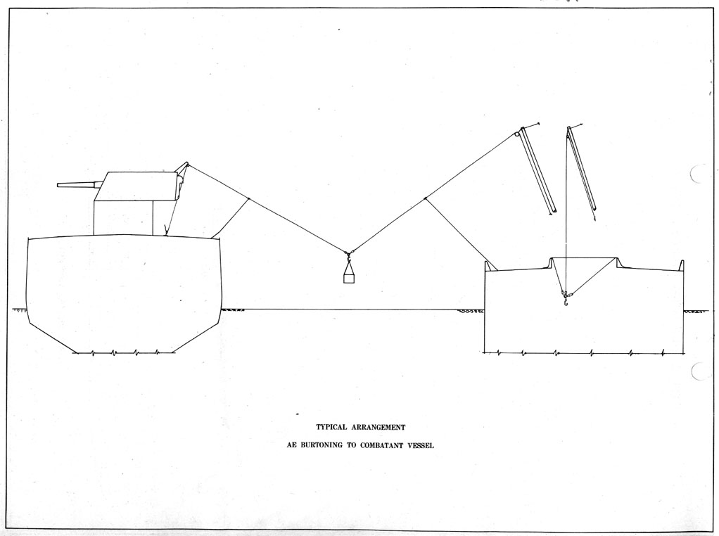
(d) FOMALHAUT (AK22), C-l-A Type (e) NITRO (AE2) 52. Pacific Fleet combatant ships of classes to which the recommended towing and transfer procedure sketches are applicable are listed below for assistance in identifying by classes and hull numbers:
|
|||||||||||||||||||||||||
|
CONFIDENTIAL
Rigging and Gear for Combatant Ships 53. In general, the AE will furnish one whip, the skip box, and all slings and linkage for each transfer station. The combatant vessel will furnish one whip with a snap-hook to be married to the AE whip above the cargo hook. All handling gear required by the combatant vessels will be furnished by them. All handling gear required for the AE's will be furnished by them. Material Required by Combatant Vessel (a) Wire rope whips, high test, plow steel, 5/8" dia., 6 x 37 lay, 300 to 400 feet length (paravane inhaul line can be used for this purpose). (b) Thrummed matting at each landing station to protect ammunition. (c) Padeyes, 1¾" dia. stock, with 20# backing plate. (d) Single sheave blocks, 10" dia. minimum, for 5/8" dia. wire rope, (paravane gear can be used for this purpose). (e) Wedges, chocks, and lines to prevent shifting of ammunition on deck. (f) Non-skid deck covering to be applied at each transfer station. (g) Stub kingposts, to be obtained from Navy Yard, Pearl Harbor, or, Commander Service Squadron TEN. (h) Handling gear as individually necessary to carry ammunition from the transfer point to magazines. 54. The minimum height of a burtoning point above the deck is fifteen feet with more being desirable. Padeyes and support points should be strong enough to withstand a temporary load of 16,000 pounds. This is based upon a 3500 pound load between two ships and probable line stresses incurred by the ships rolling apart. The transfer positions listed below for various combatant vessels, are selected to give a clear deck of sufficient area to handle the incoming ammunition, sufficient height for the support point, and proximity to a winch so that the whip may be led through snatch blocks, thereto.
|
|||||||||||||||||||||||||||||||||||||
|
CONFIDENTIAL
|
|
|
|
|
|
|
|
|
|
|
|
|
|
|
|
|
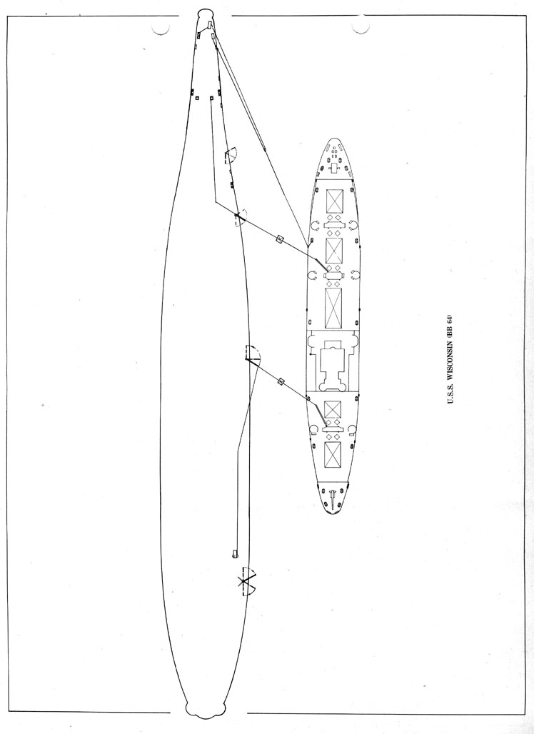
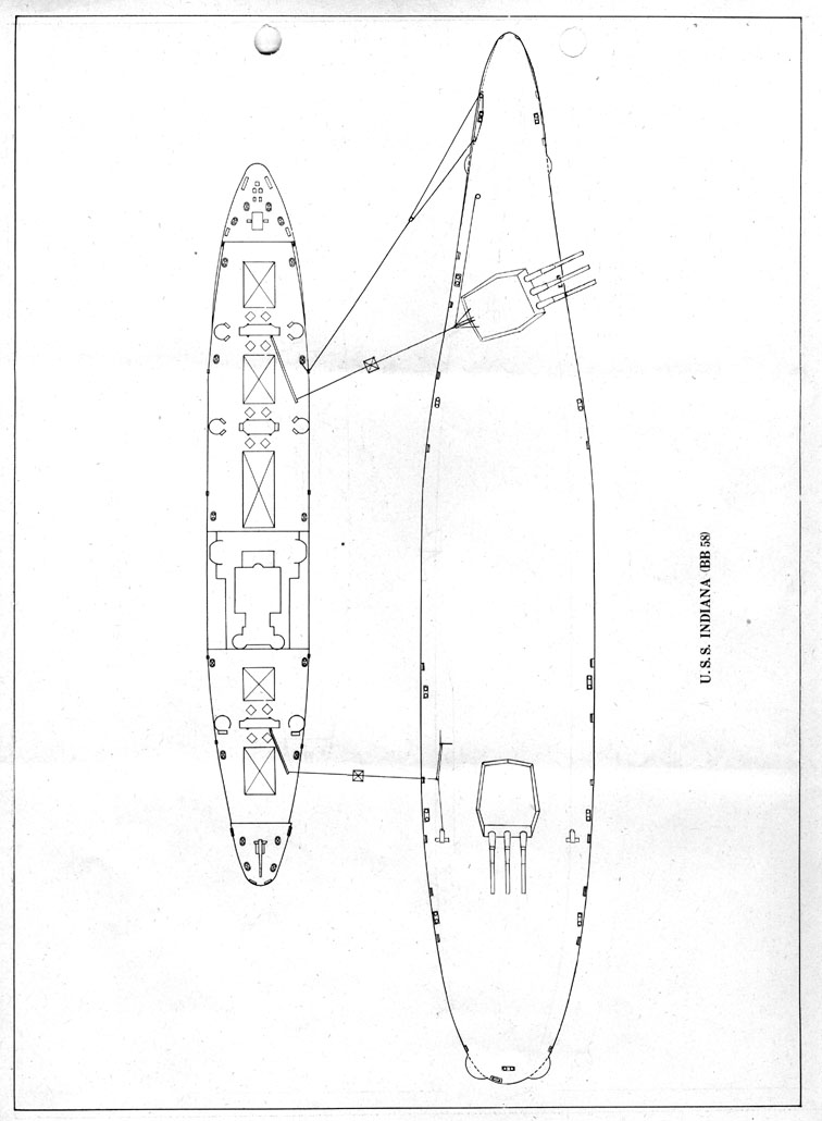
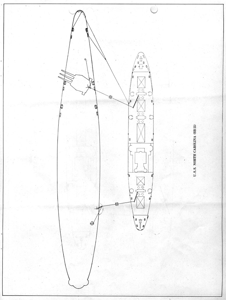
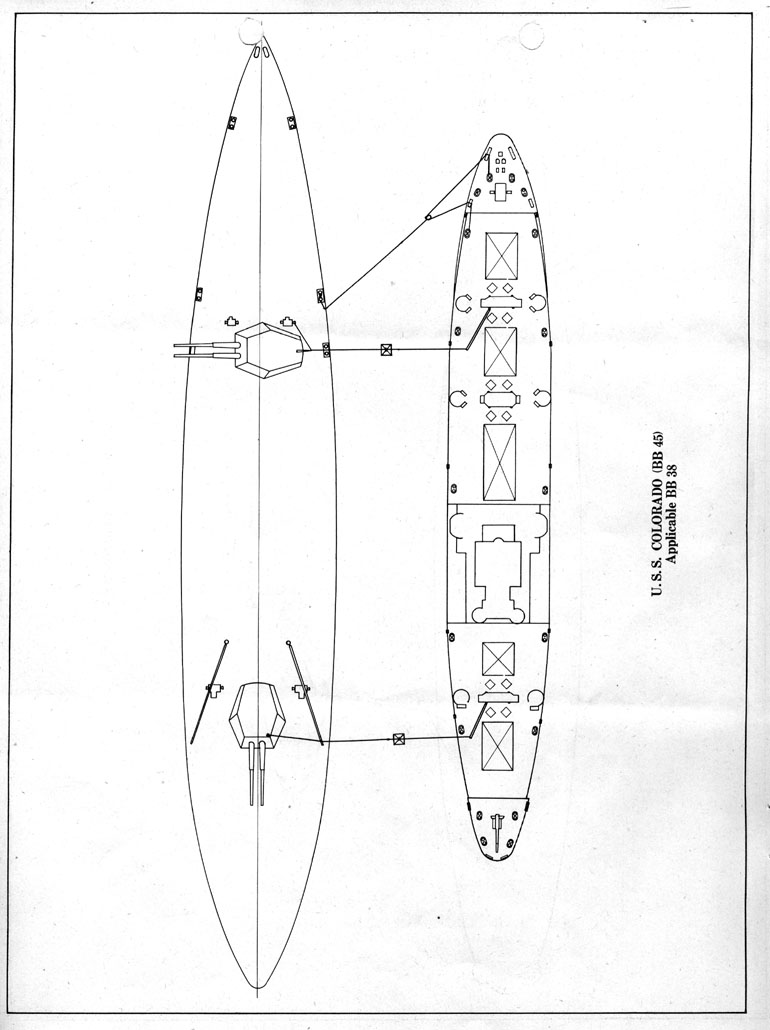
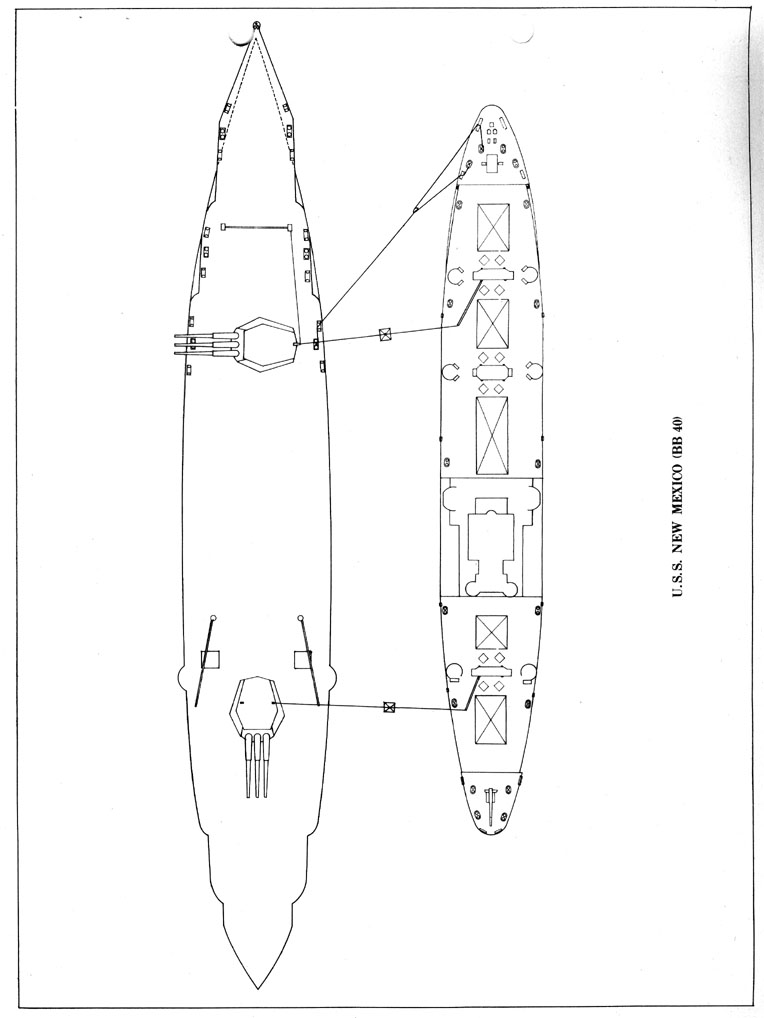
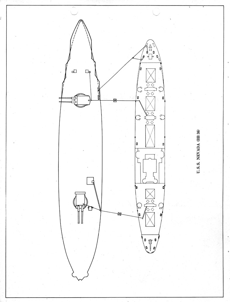
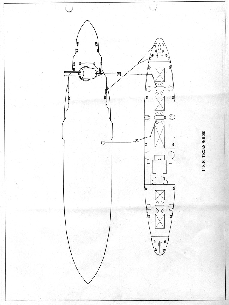
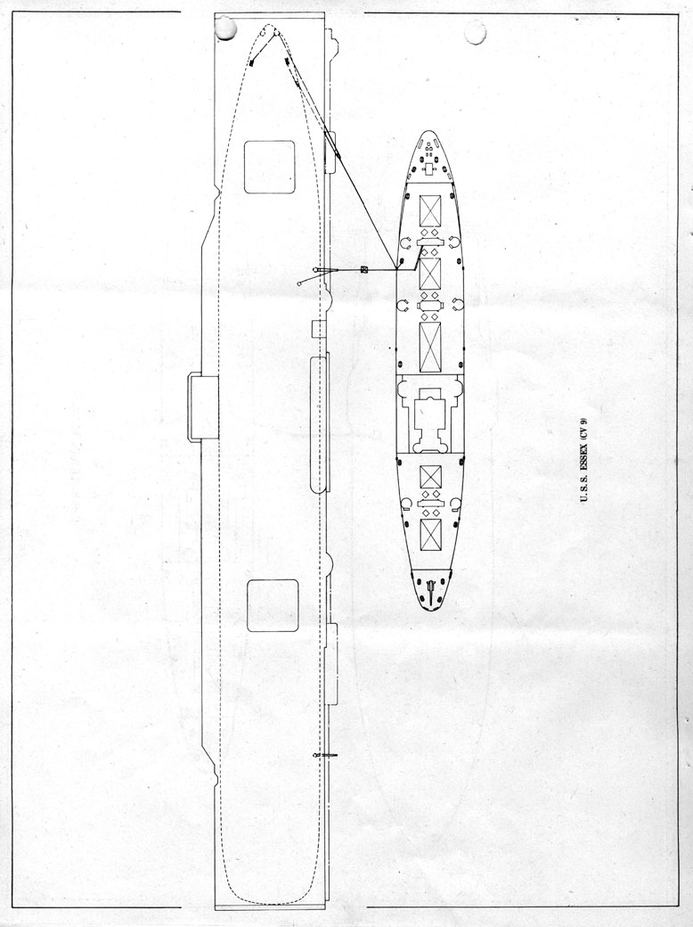
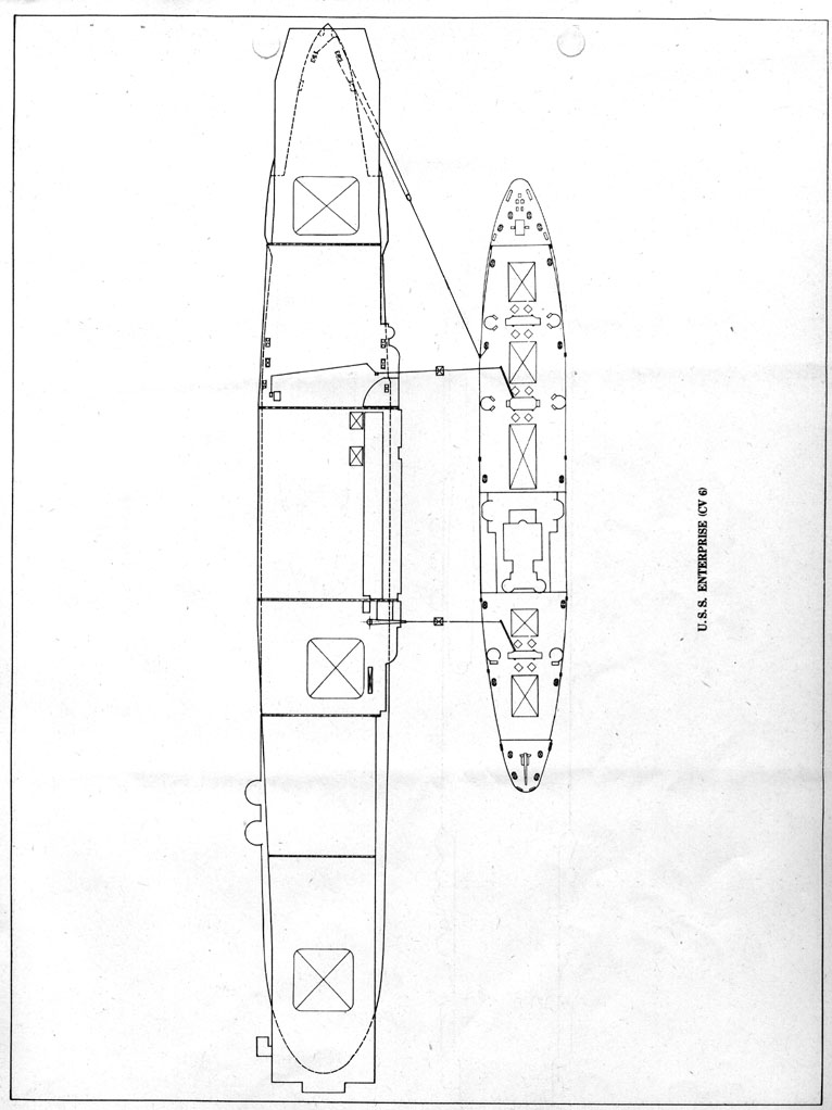
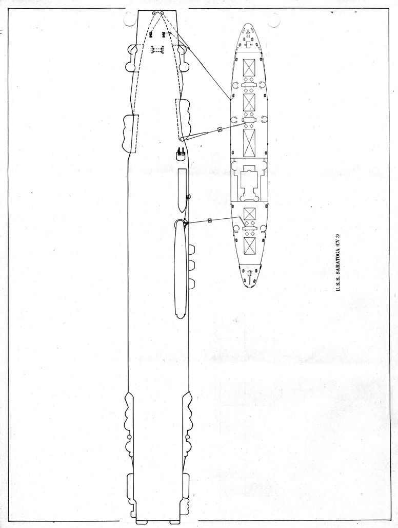
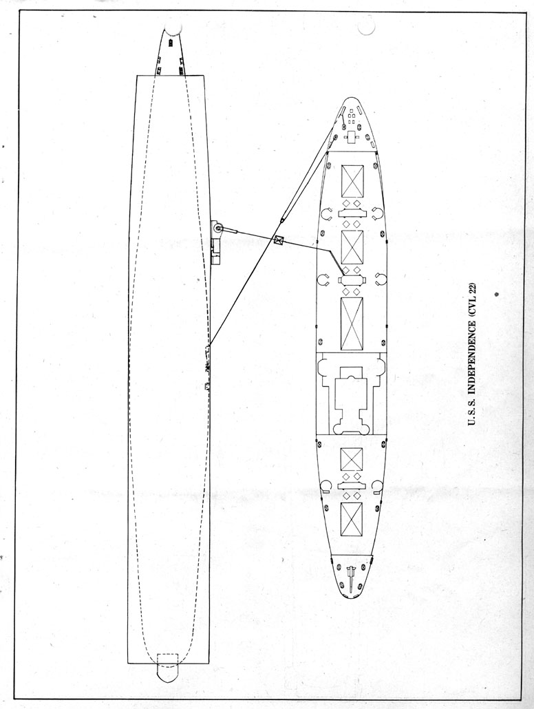
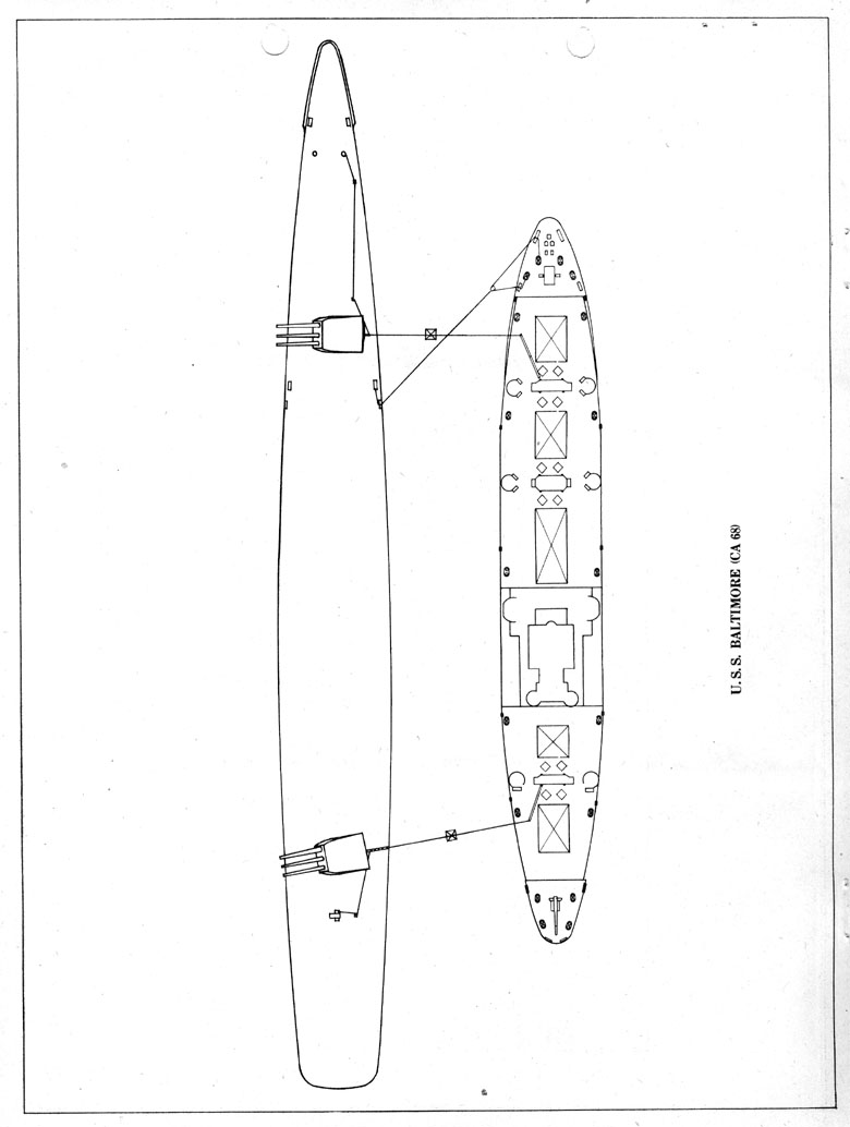
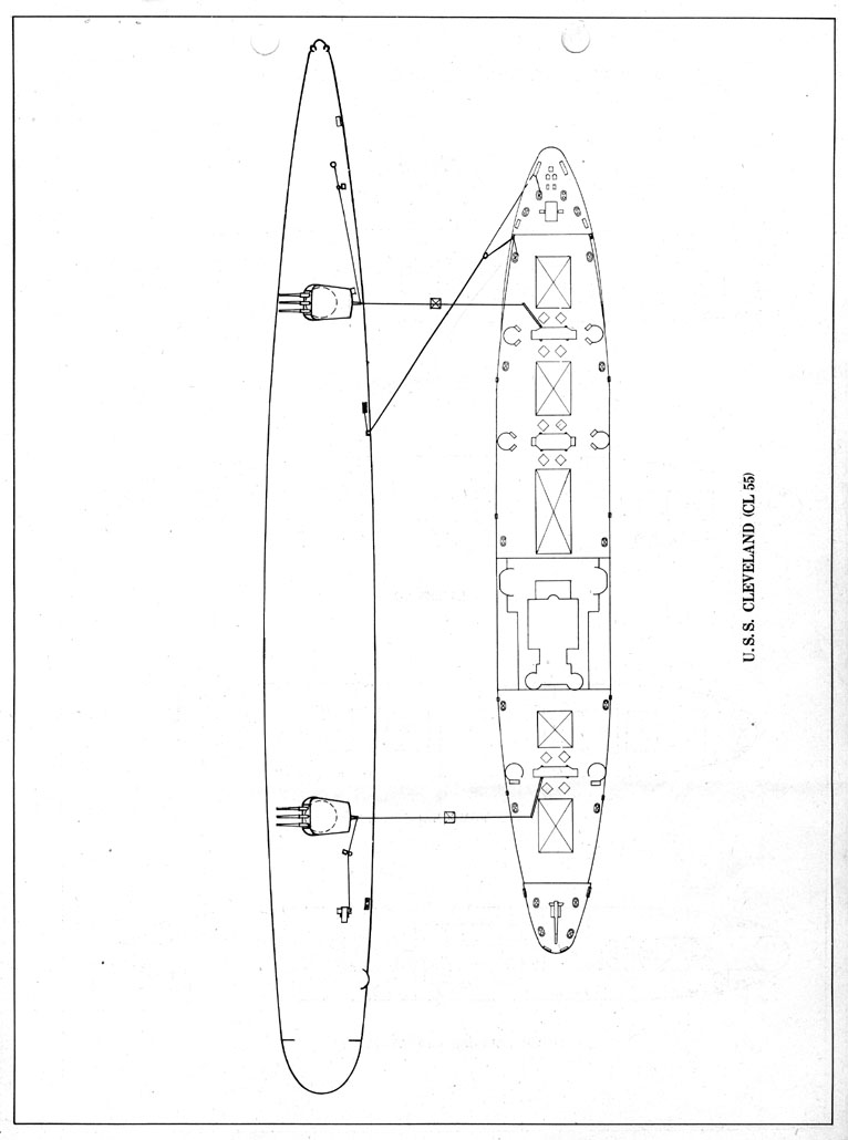
|
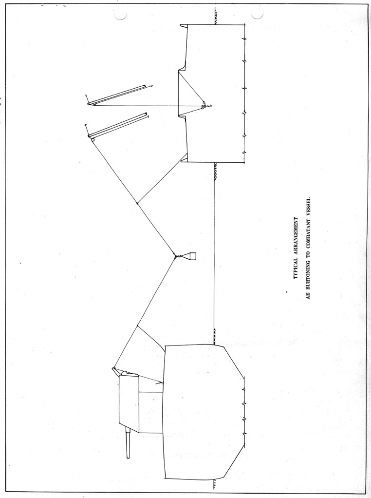
|
|
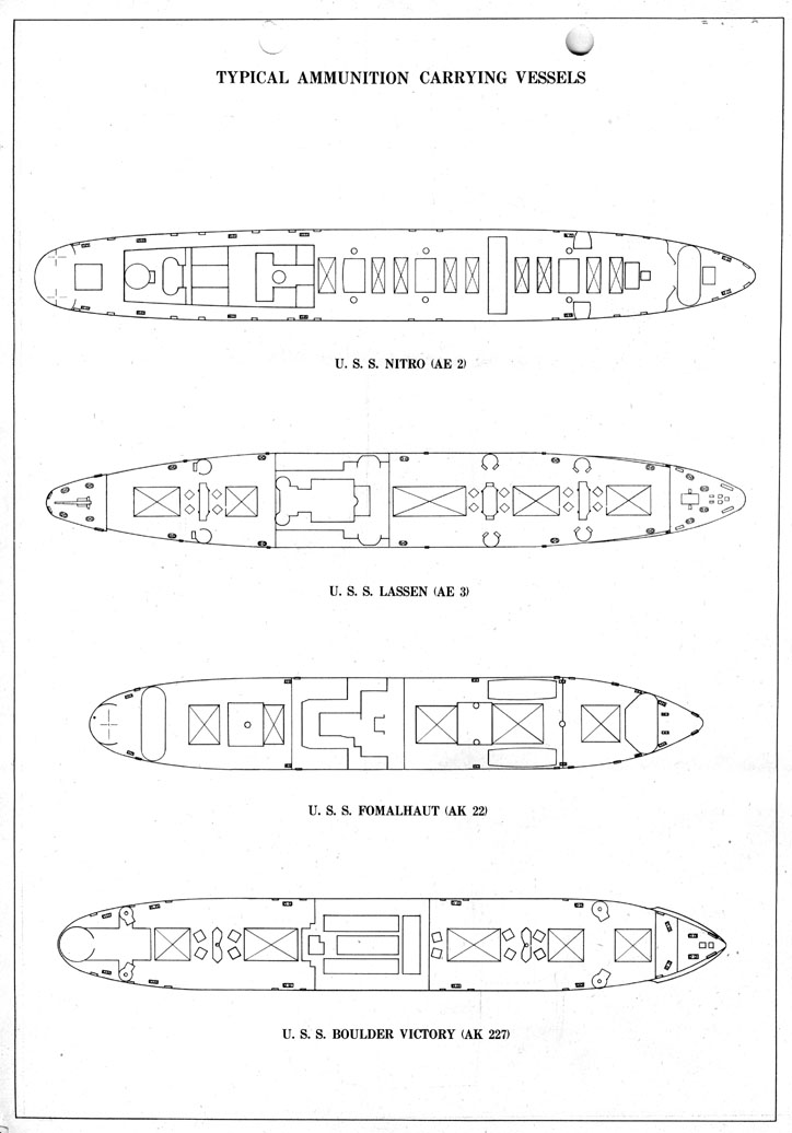
|
|
|
|
|
|
|
|
|
A rotated version of the below image can be viewed here
|
|
|
|
SOURCE:
National Archives & Records Administration, San Bruno / San Francisco Branch
Record Group 181, Pearl Harbor Navy Yard General Correspondence Files, 1941-45
Transcribed by RESEARCHER @ LARGE. Formatting & Comments Copyright R@L.
Underway Replenishment Home | Ships Home | Researcher@Large Home
